


 English
 Français
 Español
 简体中文
 简体中文
A routine method started splitting peaks minutes after a service engineer swapped a 0.005 in transfer line for a length of 0.017 in tubing he happened to have in his bag. The column, mobile phase and gradient were untouched. Roughly 40 microlitres of extra volume between the injector and the column head was enough to ruin the separation.
That is the short version of what matters with HPLC tubing: inner diameter, cut quality and fitting make-up decide the outcome far more than the name on the coil. Material decides whether your analytes survive contact with the flow path at all. The sections below cover how to choose each variable, what the common failure modes look like, and how to specify polymer tubing for fluidic assemblies and medical devices.
Content
- 1 What HPLC Tubing Does Inside the Flow Path
- 2 Inner Diameter: The Variable That Moves Your Peaks
- 3 Materials: What Each Option Gives Up
- 4 Fittings, Ferrules and Cut Quality
- 5 Specifying Polymer Tubing for Fluidic and Medical Assemblies
- 6 About Ningbo LINSTANT Polymer Materials Co., Ltd.
- 7 Frequently Asked Questions About HPLC Tubing
- 7.1 Q1. What is the best inner diameter for HPLC tubing?
- 7.2 Q2. PEEK tubing versus stainless steel tubing, which should I use?
- 7.3 Q3. What pressure can PEEK tubing handle?
- 7.4 Q4. How do I cut HPLC tubing without creating dead volume?
- 7.5 Q5. How often should HPLC ferrules be replaced?
- 7.6 Q6. Why do peaks tail after changing tubing?
What HPLC Tubing Does Inside the Flow Path
Tubing in a liquid chromatograph does three jobs at once. It contains system pressure, it keeps extra-column volume low, and it must not adsorb, catalyse or leach into the stream passing through it. A connection that is chemically perfect but physically too wide will broaden peaks; a connection that is narrow and inert but badly cut will leak at pressure.
Vendor selection guides put numbers on the first two requirements. For high-efficiency narrow-bore columns, 0.12 mm (about 0.005 in) ID tubing is the standard recommendation, while conventional 4.6 mm columns tolerate 0.17 mm (0.007 in) ID. Anything wider adds mixing volume that the column cannot undo.
The arithmetic is unforgiving. A 0.020 in ID line holds about 203 microlitres per metre, while 0.005 in ID holds 12.7 microlitres per metre. Ten centimetres of the wide line therefore adds roughly 20 microlitres, which is about 1.2 percent of the 1.6 mL void volume of a 150 x 4.6 mm column packed with 5 micrometre particles. Put the same 20 microlitres on a 150 x 2.1 mm column and it becomes close to 6 percent of the void volume, which is enough to visibly degrade resolution on early-eluting peaks.
Inner Diameter: The Variable That Moves Your Peaks
Smaller ID means less dispersion but higher back pressure, and the penalty is severe because pressure drop scales with the fourth power of the internal radius. Halving the ID multiplies the pressure drop by sixteen for the same flow and length. The two charts below show both sides of that trade-off for typical connection sizes.
Pressure drop per metre of tubing (water, 1 mL/min, 25 °C)
Bars use a logarithmic scale because the values span more than three orders of magnitude. Figures are calculated from the Hagen-Poiseuille relation for water at 25 °C; real mobile phases with higher viscosity raise every value proportionally.
Internal volume of a tubing run, by inner diameter
0.005 in ID: 12.7 µL/m0.010 in ID: 50.7 µL/m0.020 in ID: 202.7 µL/m
- Match ID to column format: 0.005 to 0.007 in for 4.6 mm columns, and 0.005 in or narrower for 2.1 mm and smaller formats.
- Keep every run as short as the instrument layout allows, because volume and pressure drop both scale with length.
- Use one ID end to end where possible; a wide segment next to a narrow one acts as a mixing chamber.
- Remember that pressure drop rises with mobile-phase viscosity, so chilled columns or viscous modifiers reach the pump limit sooner.
Materials: What Each Option Gives Up
No tubing material wins on every axis. Stainless steel is the default because it holds pressure and tolerates almost any solvent, but it can adsorb or catalyse metal-sensitive analytes. Polymer tubing solves that problem but trades away some pressure headroom, and fluoropolymers introduce creep and sealing challenges that steel users never think about.
| Tubing material | Typical role | Working pressure | Practical cautions |
|---|---|---|---|
| 316 stainless steel | Standard analytical and UHPLC connections | Routinely used in the high hundreds to thousands of bar with matched ferrules | Metal-sensitive analytes may adsorb or react; a mismatched ferrule causes leaks or dead volume |
| PEEK | Metal-free, biocompatible flow paths | Typically a few hundred bar, falling as temperature and ID rise | Solvent compatibility limits with some chlorinated solvents and DMSO; lower ceiling than steel |
| PTFE and FEP | Low-pressure transfer and corrosive service | Low pressure only, well below 30 bar in most configurations | Creeps under sustained load; ends must be cut squarely to seal |
| Polyimide-coated fused silica | High-efficiency, low-dispersion connections | High pressure when the end is prepared correctly | Fragile; damaged coating or a chipped cut end causes breakage |
316 stainless steelPEEKPTFE / FEP
The choice between the two polymer workhorses is common enough to deserve its own comparison; we keep a plain-language breakdown of PTFE versus PEEK tubing for teams that are still deciding. The short answer is that PEEK wins wherever pressure and dimensional stability matter, and PTFE wins wherever chemical resistance and low cost per metre matter more.
Fittings, Ferrules and Cut Quality
Fitting manufacturers reduce most HPLC tubing complaints to two root causes: leaks and dead volume. Both usually trace back to the same place, a ferrule that does not seal at the tube tip or an end that is not square to the axis.
- Cut with a purpose-made tubing cutter rather than a blade or side cutters; an angled or burred end will not seal, and no amount of torque will fix it.
- Seat the ferrule on the first connection and keep nut-and-ferrule pairs together; a ferrule reused on a different port is a reliable source of weeping leaks.
- Follow the manufacturer's tightening routine. Polymer nuts deform permanently when over-tightened, and steel ferrules that are only hand-tight will slip under pressure.
- Watch the ferrule seat for dead volume: if the tube bottoms out before the ferrule engages, the leftover gap becomes a mixing chamber right in front of the column.
- Pressure-test with a restriction capillary in place of the column before you commit a real method to a new connection.
Specifying Polymer Tubing for Fluidic and Medical Assemblies
The materials used in HPLC flow paths, PEEK, PTFE, FEP, PFA and polyimide, are the same polymer families that medical device manufacturers specify for catheter shafts, liners and reinforced sheaths. That overlap is not a coincidence: both applications reward tight dimensional tolerance, clean cut ends and batch-to-batch consistency.
Ningbo LINSTANT Polymer Materials Co., Ltd. extrudes exactly those materials. Our tubing catalogue covers PEEK tubing, polyimide tubing, PTFE and other fluoropolymer extrusions, multilayer and multilumen constructions, and reinforced or braided shafts, with secondary operations such as cutting, tipping and heat shrinking available in the same workflow. Typical tolerance requirements on ID and wall thickness are discussed at the quotation stage rather than assumed, because a 0.02 mm variation matters more in a 0.5 mm capillary than in a 12 mm drain line.
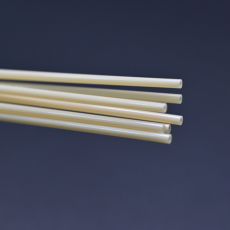 PEEK Tubing for High-Temperature Medical and Aerospace ApplicationsPEEK tubing offers tight tolerances, high-temperature stability, and biocompatibility for cardiovascular, spinal, and other demanding medical applications.View Product →
 PTFE Extrusion Tubing for Catheters and Delivery SystemsPTFE extrusion tubing combines lubricity, chemical resistance, and biocompatibility, making it relevant for catheters, intravascular delivery systems, and disposable accessories.View Product →
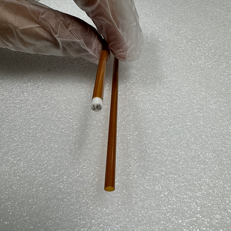 Medical Polyimide Tubing for Small-Diameter Catheter ComponentsMedical polyimide tubing supports thin walls, small inner diameters, and high-temperature resistance for catheters, electrophysiology, and stent delivery systems.View Product →
Medical device teams also use liquid chromatography during quality control, for example when quantifying a drug coating on a balloon surface or checking residual monomers after sterilisation. The tubing inside the fluidic path of that instrument and the tubing inside the device being tested come from the same material science, which is why we treat dimensional consistency and traceability as one problem rather than two.
If your project needs a custom extrusion, coating or a fully outsourced assembly, our OEM and ODM development service covers design support through to serial production under an ISO 13485:2016 quality system.
About Ningbo LINSTANT Polymer Materials Co., Ltd.
Ningbo LINSTANT Polymer Materials Co., Ltd. was established in 2014 and has since grown into a national-level high-tech enterprise with over 500 professional staff members. The company is committed to transcending the role of a traditional component supplier, striving to become an integral part of its customers' products. From precise matching during the collaborative design phase to reliability assurance during manufacturing, LINSTANT deeply integrates into the core value chain of its customers' products, transforming catheter technology into a core competitive advantage for their products.
Through continuous technological innovation and stringent quality control, we are capable of providing medical device companies with safer, more precise, and more technologically advanced customised catheter system solutions.
Frequently Asked Questions About HPLC Tubing
Q1. What is the best inner diameter for HPLC tubing?
Use 0.005 to 0.007 in ID for 4.6 mm columns and 0.005 in or narrower for 2.1 mm formats. Always pick the smallest ID the pump pressure can support.
Q2. PEEK tubing versus stainless steel tubing, which should I use?
PEEK for metal-sensitive analytes and biocompatible paths, stainless steel where you need maximum pressure and solvent tolerance. Check solvent compatibility before switching.
Q3. What pressure can PEEK tubing handle?
Commonly a few hundred bar, with the exact limit depending on ID, wall thickness and temperature. It is always lower than a matched stainless steel connection.
Q4. How do I cut HPLC tubing without creating dead volume?
Use a dedicated tubing cutter, inspect the end under magnification, and discard any cut with a burr or bevel. Square ends seat ferrules properly.
Q5. How often should HPLC ferrules be replaced?
Replace them whenever a connection is moved to a different port, or at the first sign of weeping. Ferrules are consumables, not permanent hardware.
Q6. Why do peaks tail after changing tubing?
Usually extra-column volume from a wider ID, an over-long run, or a gap at the ferrule seat. Measure the volume and shorten the path before touching the method.


