


 English
 Français
 Español
 简体中文
 简体中文
A UHPLC system running at 600 bar through a 10 cm length of 0.005 in. ID tubing is holding roughly 1.3 µL of mobile phase inside that line. Replace it with the same length of 0.020 in. ID tubing and the line holds about 20 µL. Nothing else changed, yet peak widths, retention times and apparent plate count all move. That is the practical case for treating UHPLC tubing as a system component rather than plumbing: internal diameter drives dispersion, material drives chemical compatibility, and the quality of the cut decides whether the fitting seals or weeps.
What follows sets out how those three factors interact, which numbers belong on a specification sheet, and where the realistic limits sit for polymer and stainless steel tubing.
Content
- 1 UHPLC Tubing and the Extra-Column Volume Budget
- 2 Internal Diameter: A Fourth-Power Trade-Off
- 3 Material Choice: PEEK, PTFE, FEP, PFA, ETFE and Stainless Steel
- 4 Tolerances, Cut Quality and Fittings
- 5 What Belongs on a Tubing Drawing
- 6 The Manufacturing Side: Extrusion Tolerance Is the Product
- 7 Frequently Asked Questions About UHPLC Tubing
- 7.1 Q1. What is UHPLC tubing, and how does it differ from HPLC tubing?
- 7.2 Q2. What ID tubing should I use for UHPLC?
- 7.3 Q3. Is PEEK tubing suitable for UHPLC?
- 7.4 Q4. PEEK or stainless steel tubing for UHPLC?
- 7.5 Q5. How do I cut PEEK tubing without creating dead volume?
- 7.6 Q6. Why does retention time shift after I replace tubing?
UHPLC Tubing and the Extra-Column Volume Budget
Extra-column volume is the sum of the injector, the tubing between injector and column, and the detector cell. Chromatography troubleshooting literature commonly advises keeping that total below roughly 10 to 15 µL when the column is packed with sub-2 µm particles, because such columns produce very narrow peaks and any volume outside the column dilutes and broadens them.
Tubing volume is easy to calculate and easy to underestimate: V = π r² L. Because the radius is squared, doubling the ID quadruples the volume at the same length. The chart below shows what that means across the bore sizes normally stocked for analytical work.
Two habits follow. Keep the injector-to-column run as short as the autosampler geometry allows, since a 5 cm jumper holds a quarter of what a 20 cm jumper holds at the same ID. And do not use a single bore everywhere: the low-pressure side of the system, including pump inlet, degasser and waste lines, can carry 0.020 in. or larger tubing without penalty, because dispersion there never reaches the detector.
Internal Diameter: A Fourth-Power Trade-Off
Narrow tubing reduces dispersion but costs pressure. Flow through a small bore follows the Hagen-Poiseuille relation, in which pressure drop is inversely proportional to the fourth power of the radius. Halving the ID multiplies the pressure drop by sixteen, which is why the last few centimetres before the column are both the most sensitive part of the flow path and the part most likely to trip a pressure limit.
Working ranges that hold up in routine UHPLC practice:
- 0.0025 in. to 0.005 in. ID for the injector-to-column line, where dispersion has the largest effect on peak shape.
- 0.005 in. to 0.010 in. ID from column to detector, where a slightly larger bore is usually an acceptable trade for lower back pressure.
- 0.020 in. ID and above for pump inlet, waste and any low-pressure transfer line.
Material Choice: PEEK, PTFE, FEP, PFA, ETFE and Stainless Steel
Material selection usually comes down to two questions: what is in the mobile phase, and what is being detected.
PEEK: the metal-free default
PEEK is the standard choice for the injector-to-column run in metal-sensitive work. It is biocompatible, it does not leach iron or nickel into the flow path, and it tolerates the phosphate buffers and ion-pairing reagents that cause trouble with stainless steel. It also has limits: PEEK swells in DMSO, THF and dichloromethane, and concentrated acids attack it. Datasheets for small-ID PEEK tubing commonly quote pressure ratings between roughly 5,000 and 7,000 psi (about 345 to 480 bar) at room temperature, which covers most UHPLC method conditions.
PTFE and FEP: the low-pressure side
Fluoropolymers cover the parts of the flow path where pressure is modest and chemical resistance matters most. PTFE and FEP are effectively inert to almost every mobile phase, they are soft and easy to route, and they are the usual material for pump inlet lines, degasser connections and waste. Their pressure ceiling is a fraction of PEEK's, so they are not a substitute for a high-pressure jumper.
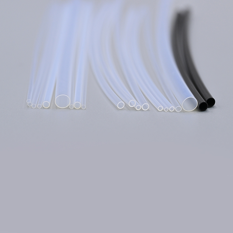 PTFE Extrusion Tube for Medical and Fluid-Path ApplicationsChemically resistant fluoropolymer tubing for low-pressure flow paths, with biocompatibility, wide temperature range, and catheter or delivery-system uses.View Product →
PFA and ETFE: where temperature or stiffness matter
PFA holds its mechanical properties at higher temperatures than FEP, which matters when tubing sits close to a column oven. ETFE is stiffer and more abrasion-resistant than PTFE at comparable chemical resistance, so it is often chosen for lines that are handled repeatedly during maintenance.
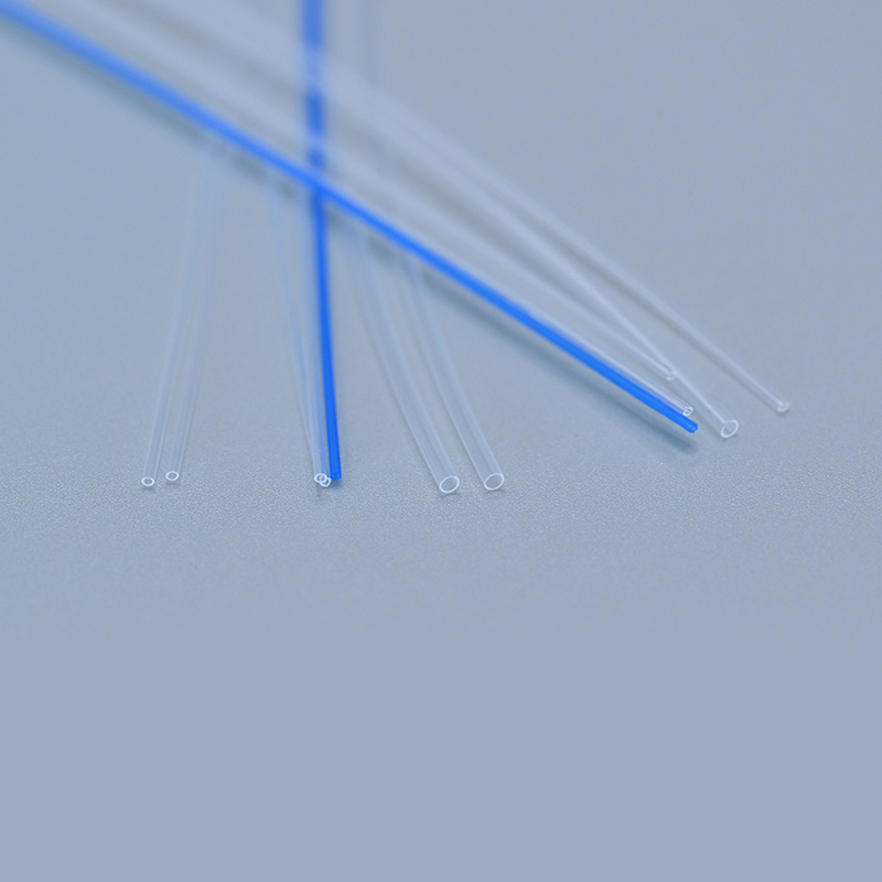 PFA Medical Extrusion Tube for Analytical and Industrial Fluid LinesFluoropolymer tubing for food-grade fluid transfer and precise analytical connections, combining chemical resistance with performance near heated instrumentation.View Product →
Stainless steel: the pressure ceiling
316 stainless steel in 1/16 in. OD reaches pressures up to about 20,000 psi with correctly made connections, which is why systems running continuously above 1,000 bar usually stay with it. The trade-offs are real: metal ions can leach into high-salt mobile phases, and analytes that chelate metals can adsorb on the wall.
| Material | Typical ID range | Working pressure | Solvent and analyte notes | Best fit |
|---|---|---|---|---|
| PEEK | 0.0025 to 0.030 in. | Commonly quoted 5,000 to 7,000 psi for small IDs | Swelling in DMSO, THF and dichloromethane; avoid concentrated acids; metal-free | Injector-to-column lines, metal-sensitive analytes |
| PTFE | 0.010 to 0.062 in. | Low pressure, below a few hundred psi | Widest chemical resistance; soft and easily routed | Pump inlet, waste, low-pressure transfer |
| FEP | 0.010 to 0.062 in. | Low pressure | Similar chemistry to PTFE, transparent wall | Degasser and detector waste lines |
| PFA | 0.010 to 0.062 in. | Low to moderate | Fluoropolymer inertness with better high-temperature stability | Lines near a column oven |
| ETFE | 0.010 to 0.062 in. | Low to moderate | Good chemical resistance with higher stiffness | Lines handled during maintenance |
| 316 stainless steel | 0.0025 to 0.020 in. | Up to about 20,000 psi with correct fittings | Can release metal ions in high-salt or ion-pairing methods | Systems running above 1,000 bar |
Where the choice is genuinely close, a side-by-side comparison of PTFE and PEEK tubing against your mobile phase list is usually the fastest way to settle it.
Tolerances, Cut Quality and Fittings
Two items on a tubing drawing decide whether a method transfers cleanly between instruments: ID tolerance and cut quality.
ID tolerance is written either as an absolute figure, such as +/-0.0005 in. (about +/-13 µm), or as a percentage of nominal. Because volume scales with the square of the diameter, tolerance converts directly into a volume swing, and the swing is proportionally larger on a small bore than on a large one.
Cut quality is the second half of the problem. A tube cut at an angle, or left with a burr on the end, cannot seat squarely against the cone of a 10-32 port. The result is a small trapped volume directly in front of the column, a classic cause of extra peak width that no amount of column conditioning will remove. A cutter with a razor-edged guide produces a square, burr-free face; a diagonal cutter does not.
Fittings finish the assembly. 1/16 in. OD is standard for 10-32 coned ports, and finger-tight PEEK nuts are the usual choice for PEEK tubing because they seal reliably and can be re-used. Over-tightening is the common mistake: it cold-flows the polymer, narrows the bore at the connection, and quietly adds both back pressure and dead volume.
What Belongs on a Tubing Drawing
A specification that survives a supplier change carries six items: material grade and colourant, nominal ID with tolerance, OD, cut length with tolerance, cut-face condition, and cleanliness or extractables requirements for the intended detection mode.
OD and ID are the numbers buyers check first, yet they are the two least often written with a tolerance attached. On a 0.005 in. bore, the difference between +/-0.0005 in. and an unspecified tolerance is a twenty percent swing in line volume, which is large enough to shift retention time when tubing is replaced between instruments.
The Manufacturing Side: Extrusion Tolerance Is the Product
Ningbo LINSTANT Polymer Materials Co., Ltd. was established in 2014 and has since grown into a national-level high-tech enterprise with over 500 professional staff members. The company is committed to transcending the role of a traditional component supplier, striving to become an integral part of its customers' products. From precise matching during the collaborative design phase to reliability assurance during manufacturing, LINSTANT deeply integrates into the core value chain of its customers' products, transforming catheter technology into a core competitive advantage for their products.
Through continuous technological innovation and stringent quality control, we are capable of providing medical device companies with safer, more precise, and more technologically advanced customised catheter system solutions.
For anyone specifying precision polymer tubing, the relevant capabilities are these: a GMP-compliant cleanroom facility of close to 20,000 m², 15 imported extrusion lines with single, double and triple co-extrusion, eight dedicated PEEK extrusion lines, ISO 13485:2016 certification, and OEM/ODM programmes that work from a drawing and a tolerance stack rather than a catalogue number.
Frequently Asked Questions About UHPLC Tubing
Q1. What is UHPLC tubing, and how does it differ from HPLC tubing?
Same job, tighter numbers. UHPLC systems run at higher pressures with sub-2 µm columns, so the line between injector and column normally has a smaller ID, typically 0.0025 to 0.005 in., and a tighter ID tolerance than a conventional HPLC line.
Q2. What ID tubing should I use for UHPLC?
Use 0.0025 to 0.005 in. from injector to column, 0.005 to 0.010 in. from column to detector, and 0.020 in. or larger on the low-pressure side such as pump inlet and waste.
Q3. Is PEEK tubing suitable for UHPLC?
Yes, for most method conditions, and it is the usual answer when the flow path must be metal-free. Check solvent compatibility first, since PEEK swells in DMSO, THF and dichloromethane, and stay inside the pressure rating for the specific ID.
Q4. PEEK or stainless steel tubing for UHPLC?
Stainless steel handles the highest pressures, up to about 20,000 psi with correct fittings, but can release metal ions and interact with ion-pairing reagents. PEEK is inert and biocompatible, with a lower pressure ceiling and solvent restrictions.
Q5. How do I cut PEEK tubing without creating dead volume?
Use a cutter with a razor-edged guide so the face is square and burr-free, then inspect the end before installing it. An angled or burred cut will not seal flat against the port cone and leaves a trapped volume ahead of the column.
Q6. Why does retention time shift after I replace tubing?
Usually a change in extra-column volume or ID tolerance. A longer line or a larger bore adds volume and broadens peaks; an out-of-tolerance bore does the same thing less predictably, which is why the tolerance belongs on the purchase order.


