NINGBO LINSTANT POLYMER MATERIALS CO., LTD. NINGBO LINSTANT POLYMER MATERIALS CO., LTD.
  • CUSTOMIZED FOR
    YOUR BUSINESS
    Tailored for a Wide Range of Applications
  • Research and Design
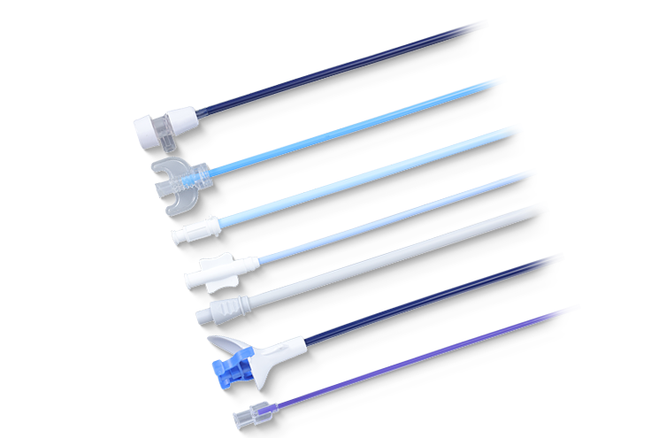
    With an in-depth understanding of the properties of polymer materials and the application requirements of medical catheters, we leverage our extensive experience in R&D and design to offer constructive material selection and design recommendations tailored to your needs.
    READ MORE
  • Rapid Prototyping
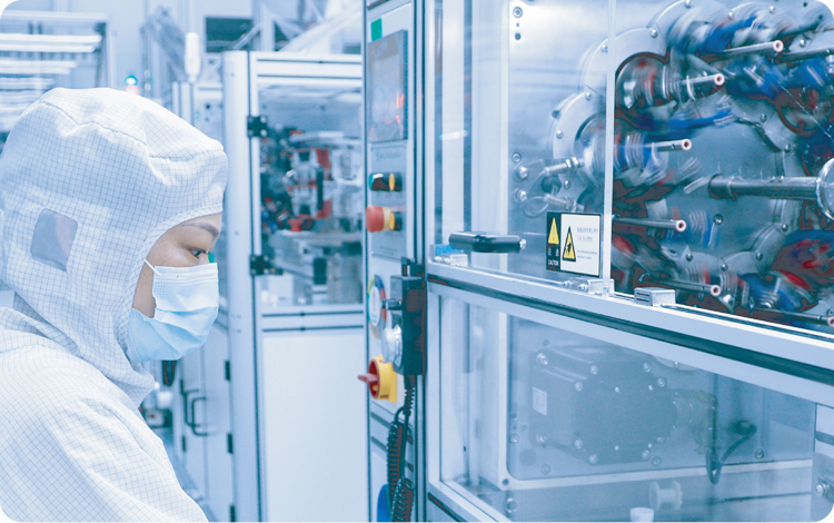
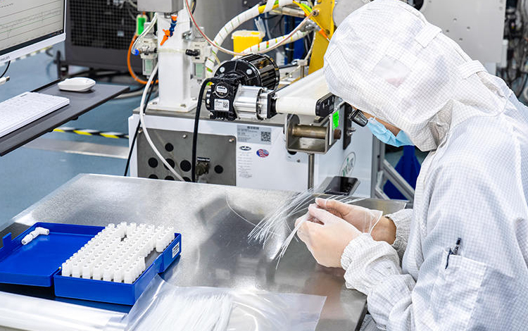
    Equipped with a comprehensive production process system and advanced processing equipment, we adhere to design specifications to swiftly manufacture prototypes. We maintain frequent and in-depth communication with you to ensure that the appearance quality, dimensional accuracy, and basic performance indicators of the prototypes meet your design expectations. Additionally, our rapid prototyping line enables fast sampling, saving you time and costs.
    READ MORE
  • Testing & Validation
    We collaborate with your validation processes and provide the samples and documentation required for clinical trials and other regulatory needs. We also offer professional guidance on product and regulatory matters.
    READ MORE
  • Certification Assistance
    We are certified to ISO 13485 quality management system. Our robust quality management system provides comprehensive support to ensure that all documentation complies with regulatory requirements, facilitating a smooth product certification process.
    READ MORE
  • Mass Production
    We have a mature production management system and strictly follow standardized processes to ensure timely, high-quality, and accurate delivery. In the event of quality issues, we immediately initiate a traceability mechanism to pinpoint the root cause and implement swift corrective actions, ensuring that every product entering the market meets stringent quality standards.
    READ MORE
NINGBO LINSTANT POLYMER MATERIALS CO., LTD.
  • NINGBO LINSTANT POLYMER MATERIALS CO., LTD.
  • NINGBO LINSTANT POLYMER MATERIALS CO., LTD.
  • NINGBO LINSTANT POLYMER MATERIALS CO., LTD.
  • NINGBO LINSTANT POLYMER MATERIALS CO., LTD.
  • NINGBO LINSTANT POLYMER MATERIALS CO., LTD.
  • NINGBO LINSTANT POLYMER MATERIALS CO., LTD.
  • NINGBO LINSTANT POLYMER MATERIALS CO., LTD.
  • NINGBO LINSTANT POLYMER MATERIALS CO., LTD.
  • NINGBO LINSTANT POLYMER MATERIALS CO., LTD.
  • NINGBO LINSTANT POLYMER MATERIALS CO., LTD.
  • NINGBO LINSTANT POLYMER MATERIALS CO., LTD.
    NINGBO LINSTANT POLYMER MATERIALS CO., LTD.
    Neurovascular
    -Micro Catheter
    -Aspiration Thrombectomy Catheter
    -Balloon Tubing
    -Guiding Catheter
    -Angiographic Catheter
    -Protection Tubing
    NINGBO LINSTANT POLYMER MATERIALS CO., LTD.
    Ophthalmic System
    -Distal Catheter
    -Lacrimal Cannula
    -Drainage Tube
  • NINGBO LINSTANT POLYMER MATERIALS CO., LTD.
    NINGBO LINSTANT POLYMER MATERIALS CO., LTD.
    Electrophysiology
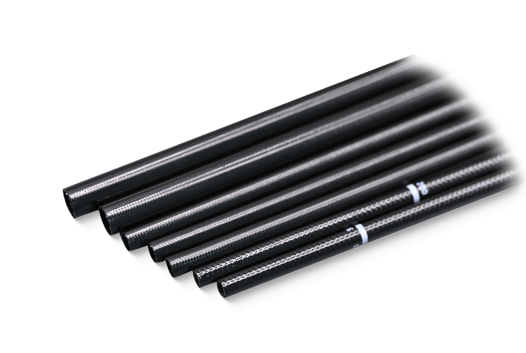
    -Braid Reinforced Tubing
    -Coil Reinforced Tubing
    -Medical Polyimide Tubing
    NINGBO LINSTANT POLYMER MATERIALS CO., LTD.
    Cardiovascular
    -Single/Double/TripleBalloon Tubing
    -Multi-lumen Tubing
    -Medical Multi-layer Tubing
    NINGBO LINSTANT POLYMER MATERIALS CO., LTD.
    Structural Heart Disease
    -Micro Catheter
    -Aspiration Thrombectomy Catheter
    -Balloon Tubing
    -Guiding Catheter
    -Angiographic Catheter
    -Introducer Sheath
  • NINGBO LINSTANT POLYMER MATERIALS CO., LTD.
    NINGBO LINSTANT POLYMER MATERIALS CO., LTD.
    Endoscope
    -Braid Reinforced Tubing
    -Coil Reinforced Tubing
    -Multi-lumen Tubing
  • NINGBO LINSTANT POLYMER MATERIALS CO., LTD.
    NINGBO LINSTANT POLYMER MATERIALS CO., LTD.
    Urinary
    -Urinary Coil Tubing
    -Steerable Urinary Coil Sheath
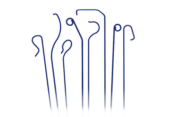
    -Stone Retrieval Basket (PI)
  • NINGBO LINSTANT POLYMER MATERIALS CO., LTD.
    NINGBO LINSTANT POLYMER MATERIALS CO., LTD.
    Minimally Invasive Surgery (MIS)
    -Balloon Tubing
    -Steerable Sheath
    -Disposable Sampling Tube
    NINGBO LINSTANT POLYMER MATERIALS CO., LTD.
    Orthopedics
    -PEEK Tubing
    -Vertebrae Balloon Tubing
    -Compression Sleeve
    NINGBO LINSTANT POLYMER MATERIALS CO., LTD.
    Peripheral Vascular
    -Braid Reinforced Tubing
    -Coil Reinforced Tubing
    -Introducer Sheath
INDUSTRIES WE SERVE
We understand challenges in various industries and provide solutions to meet your specific production needs.
READ MORE
  • NINGBO LINSTANT POLYMER MATERIALS CO., LTD.
    Head
  • NINGBO LINSTANT POLYMER MATERIALS CO., LTD.
    Chest
  • NINGBO LINSTANT POLYMER MATERIALS CO., LTD.
    Hip
  • NINGBO LINSTANT POLYMER MATERIALS CO., LTD.
    Hip1
  • NINGBO LINSTANT POLYMER MATERIALS CO., LTD.
    lower limbs
ABOUT LINSTANT
Ningbo Linstant Polymer Materials Co., Ltd. was a professional

OEM/ODM Medical Tubing Manufacturers and Medical Tubing Supplier

, established in 2014 and now employs over 400 employees. We specialize in the extrusion processing, coating, and post-processing technologies of medical polymer tubing. Our commitment to medical device manufacturers is reflected in our precision, safety, diverse processing capabilities, and consistent product quality.
READ MORE
  • 0
    Establishment time
  • 0+
    Employee
  • 0+
    Production line
NINGBO LINSTANT POLYMER MATERIALS CO., LTD.
NEWS
  • Industry News
    Jul 23,2026
    PEEK vs PTFE Tubing: Which Is Better for Medical Devices?
    Quick Answer: PEEK vs PTFE Tubing for Medical Devices PEEK tubing and PTFE tubing are suited to different roles in medical device design rather than being direct substitutes for one another. PEEK tubing offers higher mechanical strength, greater rigidity, and stable performance at temperatures above 250°C, making it well suited for structural components and repeated high-temperature sterilization, while PTFE tubing offers a lower coefficient of friction and greater flexibility, making it the preferred material for lubricious inner liners in catheter and guidewire applications. This guide compares medical PEEK tubing against PTFE and polyimide across strength, temperature resistance, and application fit, helping device engineers select the right material for a specific tubing requirement. What Is Medical PEEK Tubing? PEEK, or polyether ether ketone, is a high-performance thermoplastic polymer known for combining high strength with high fracture toughness. Medical grade PEEK tubing is produced through a precision extrusion process and is used in applications where a combination of mechanical strength, dimensional stability, and chemical resistance is required within a relatively small tubing profile. Core Material Characteristics of PEEK High strength combined with high fracture toughness, supporting structural tubing roles Stable dimensional performance across a wide temperature range Good chemical stability against most solvents used in device assembly and cleaning Flame resistance and wear resistance suited to repeated mechanical contact Good biocompatibility appropriate for medical device applications PEEK's high crystallinity is one of the main reasons behind its thermal stability, since a more ordered molecular structure resists deformation at elevated temperatures better than lower-crystallinity polymers, supporting stable operation up to 250°C. Why Is PEEK Used in Medical Devices? PEEK is selected for medical device components when a project requires structural strength that standard fluoropolymer or polyamide tubing cannot provide, particularly in applications involving repeated high-temperature sterilization or mechanical load-bearing roles. The chart below compares tensile strength across PEEK, PTFE, and polyimide tubing materials. Tensile Strength by Tubing Material (MPa) 97 MPa PEEK 231 MPa Polyimide (PI) 31 MPa PTFE While polyimide shows the highest raw tensile strength among the three materials, PEEK offers a distinct combination of strength and toughness that makes it more resistant to sudden impact fracture, a property that is often more relevant than peak tensile strength alone for components subject to repeated mechanical stress. PTFE, by comparison, is significantly softer and more flexible, which is why it is generally used for its low-friction surface properties rather than structural strength. Temperature Resistance: PEEK vs PTFE vs Polyimide Temperature performance is one of the most frequently cited reasons for selecting PEEK tubing, particularly for devices requiring repeated autoclave sterilization cycles. The line chart below shows relative mechanical stability across a rising temperature range for all three materials. Relative Mechanical Stability vs Temperature (%) 100 50 0 100C 150C 200C 250C 300C 350C Polyimide PEEK PTFE PEEK tubing maintains strong mechanical stability up through 250°C, supporting repeated high-temperature sterilization cycles without significant performance loss, which is one of its most practical advantages over PTFE. PTFE tubing shows a steeper decline as temperatures rise past its lower service ceiling, while polyimide, though it shows the strongest stability at the highest temperatures shown, is typically used in a different application category due to its distinct extrusion and coating process compared with standard PEEK and PTFE extrusion. PEEK vs PTFE vs Polyimide: Full Performance Comparison Choosing between these three materials depends on which performance attributes matter most for a specific tubing role. The radar chart below scores each material across five criteria relevant to medical tubing selection. PEEK vs PTFE vs Polyimide Rigidity Temperature Resistance Lubricity Thin-Wall Capability Fracture Toughness PEEK PTFE Polyimide PEEK scores strongest on rigidity, fracture toughness, and temperature resistance, confirming its role as a structural material for components that must resist deformation under mechanical or thermal stress. PTFE scores highest on lubricity by a wide margin, which is why it remains the standard choice for inner-lumen surfaces where guidewires or other devices need to slide with minimal friction. Polyimide occupies a middle position with an emphasis on thin-wall capability and strong temperature resistance, making it better suited to very small-diameter structural applications such as microcatheter shafts, where PEEK's typical wall thickness may be less practical. Material Property Reference Table The table below summarizes general reference properties across the three materials to support early-stage material selection. General property comparison of PEEK, PTFE, and polyimide medical tubing materials Property PEEK PTFE Polyimide Long-Term Operating Temperature Up to 250°C Up to 260°C Above 350°C Relative Rigidity High Low High Coefficient of Friction Moderate Very Low Moderate Typical Wall Thickness Range Standard to thick-wall Standard Ultra thin-wall Biocompatibility Good Good Good Sterilization and Biocompatibility Considerations Repeated sterilization compatibility is a common deciding factor when choosing between PEEK and PTFE for reusable or high-temperature-processed device components. PEEK's high crystallinity and thermal stability allow it to withstand repeated autoclave sterilization cycles above 250°C without significant dimensional drift, an advantage for reusable instrument components that undergo many sterilization cycles over a device's service life. Biocompatibility evaluation for both materials is generally assessed against ISO 10993, the international standard for biological evaluation of medical devices, which addresses cytotoxicity, sensitization, and irritation testing relevant to tubing with patient contact (International Organization for Standardization, ISO 10993). Both PEEK and PTFE tubing intended for medical use are typically evaluated under this framework prior to device integration. Where Medical PEEK Tubing Is Applied PEEK tubing is specified across several device categories where structural strength and thermal stability outweigh the need for extreme flexibility or low friction. The table below outlines common application areas. Common medical device applications for PEEK catheter and instrument tubing Device Category Primary Requirement Why PEEK Is Selected Introducer sheaths Structural rigidity, kink resistance High strength at moderate wall thickness Reusable surgical instrument components Repeated autoclave sterilization Stable above 250°C Catheter shaft components Pushability, dimensional stability High strength and fracture toughness Fluid handling components Chemical resistance Stable against most solvents In many multi-material catheter designs, PEEK is used alongside PTFE rather than in place of it, with PEEK providing structural support in an outer or intermediate layer while PTFE forms the inner lumen surface, combining the strengths of both materials in a single device. Custom PEEK Tubing Options Custom medical PEEK tubing projects typically involve adjusting dimensional and processing parameters to fit a specific device requirement. Precision extruded PEEK tubing can be tailored across several variables. Inner and outer diameter tuning to match a specific catheter or instrument profile Wall thickness adjustment to balance rigidity against flexibility for a given application Surface treatment options to support bonding with adjacent device components Color coding for multi-component or multi-lumen device assemblies Because PEEK combines hardness with toughness, custom tubing projects can often achieve a thinner wall than would be structurally reliable in a less rigid material, supporting more compact device designs without sacrificing mechanical performance. Working With a PEEK Tubing Manufacturer: What to Verify Sourcing medical PEEK tubing requires confirming a supplier's extrusion precision, quality documentation, and application-specific experience, since PEEK's high melt temperature and crystallinity make it more demanding to process consistently than many other medical polymers. Confirmation of ISO certification and a documented quality management system Precision extrusion capability suited to PEEK's processing requirements Experience producing custom PEEK extrusion at the specific diameter range required Support for OEM and ODM development workflows, including sample iteration before full production Ningbo Linstant Polymer Materials Co., Ltd. has operated since 2014 as a professional OEM and ODM medical tubing manufacturer and supplier, now employing over 400 employees across extrusion processing, coating, and post-processing technologies for medical polymer tubing. The company's PEEK tubing is built on material combining hardness with toughness, offering high precision and stable operation in environments up to 250°C, supporting repeated sterilization under high-temperature conditions. The material's high crystallinity contributes to better thermal stability, and the company's commitment to precision, safety, and consistent product quality supports device manufacturers developing structural components across catheter, instrument, and fluid handling applications. Frequently Asked Questions Q1: What is medical PEEK tubing? Medical PEEK tubing is precision-extruded tubing made from polyether ether ketone, a high-performance thermoplastic known for high strength, toughness, and thermal stability. Q2: Why is PEEK used in medical devices? PEEK is used for its combination of mechanical strength, dimensional stability, chemical resistance, and ability to withstand repeated high-temperature sterilization. Q3: Is PEEK biocompatible? Medical grade PEEK is generally evaluated against ISO 10993 biological evaluation criteria and exhibits good biocompatibility for devices with patient contact. Q4: Can PEEK tubing be sterilized? Yes, PEEK tubing withstands temperatures above 250°C, allowing for repeated sterilization under high-temperature autoclave conditions without significant dimensional drift. Q5: PEEK vs PTFE tubing, which is better? Neither is universally better: PEEK offers higher strength and temperature resistance, while PTFE offers superior lubricity, so the right choice depends on the tubing's role. Q6: PEEK vs Polyimide, what is the difference? Polyimide supports thinner walls and higher short-term temperature resistance, while PEEK offers greater fracture toughness and rigidity at standard wall thicknesses. Q7: What is PEEK used for in medical devices? PEEK is used in introducer sheaths, reusable surgical instrument components, catheter shaft sections, and fluid handling components requiring chemical resistance. Q8: Why is PEEK used in catheters? PEEK provides structural support and dimensional stability in catheter shaft components, often paired with PTFE for a lubricious inner lumen surface.
  • Industry News
    Jul 16,2026
    What Is Medical Balloon Tubing? A Complete Guide (2026)
    Quick Answer: What Medical Balloon Tubing Is and Why It Matters Medical balloon tubing is the precision-extruded polymer tube used to form the balloon body of a balloon dilatation catheter, and its wall consistency directly determines how the balloon inflates, expands, and holds pressure inside the vasculature. Tubing tolerance, wall concentricity, and layer construction are the three factors that most directly affect balloon performance, since even small variations in wall thickness can cause uneven expansion or premature failure under pressure. This guide explains how medical balloon tubing is engineered, how compliant and non-compliant constructions differ, and what specification data device engineers should reference when sourcing balloon catheter tubing for a new or existing device design. What Is Medical Balloon Tubing? Balloon tubing is a specialized extruded tube that, after a blow-molding process, forms the inflatable balloon segment of a balloon catheter. Unlike standard catheter tubing, balloon tubing must be engineered to expand predictably to a target diameter under a defined inflation pressure, then return close to its original profile when deflated, all while maintaining a consistent wall thickness around its full circumference. Key Quality Attributes of Balloon Tubing Tight dimensional tolerance to support predictable balloon expansion Good concentricity, meaning the inner and outer walls remain evenly centered Low ellipticity, meaning the tube cross-section stays close to a true circle Consistent elongation properties to support uniform blow-molding results Reliable burst pressure performance appropriate to the intended procedure Because balloon tubing tolerances are often held to within ±0.01mm, the extrusion process requires closely controlled melt temperature, draw speed, and cooling conditions, which is why balloon tubing production is typically treated as a distinct specialty within medical polymer extrusion. What Is Balloon Compliance and Why Does It Matter? Balloon compliance describes how much a balloon's diameter changes as inflation pressure increases. This behavior is determined largely by the polymer material used in the balloon tubing and how that material is processed during blow-molding. Understanding compliance helps device engineers match the balloon material to the intended clinical function, whether that is gentle vessel dilation or precise stent deployment. Compliant vs Semi-Compliant vs Non-Compliant Diameter Growth Burst Pressure Dimensional Precision Flexibility Wall Thinness Compliant Non-Compliant Semi-Compliant Compliant balloon tubing, typically made from softer materials such as nylon, shows the greatest diameter growth as pressure increases, which suits procedures where gradual, gentle expansion is preferred. Non-compliant balloon tubing, often produced from higher-modulus materials such as Pebax or PET-based constructions, maintains a much more stable diameter across a wide pressure range, making it the preferred choice for stent deployment where precise, predictable sizing is critical. Semi-compliant balloon tubing sits between the two, offering moderate diameter growth alongside good dimensional precision, which is why it remains a common general-purpose choice across several catheter applications. How Layer Construction Affects Burst Pressure Balloon tubing can be produced as a single-layer, double-layer, or triple-layer construction, and layer count is one of the strongest determinants of achievable burst pressure. Multi-layer constructions combine materials with complementary properties, such as a strength-oriented outer layer paired with a more flexible inner layer, to increase pressure resistance without significantly increasing wall thickness. Rated Burst Pressure by Layer Construction (atm) 45-55 atm Triple-Layer 28-35 atm Double-Layer 14-20 atm Single-Layer As the chart illustrates, triple-layer balloon tubing can achieve burst pressure ratings of 45-55 atm, considerably higher than single-layer constructions, which is why multi-layer designs are typically specified for high-pressure applications such as calcified lesion treatment. Double-layer constructions offer a practical middle ground, delivering meaningfully higher pressure resistance than single-layer tubing while remaining simpler to manufacture than a full triple-layer build. Single-layer tubing remains suitable for lower-pressure applications where profile simplicity and cost-efficient production are the priority. Elongation and Blow-Molding Performance Elongation behavior during the blow-molding process determines how evenly a balloon expands from its parison shape into its final target diameter. Material selection and processing parameters both influence this curve, and mismatched elongation properties are a common cause of uneven wall thickness in finished balloons. The line chart below illustrates typical relative diameter expansion as blow-molding pressure increases for two common balloon tubing material families. Relative Diameter Expansion During Blow-Molding (%) 100 50 0 Stage 1 Stage 2 Stage 3 Stage 4 Stage 5 Stage 6 Nylon-Based Tubing Pebax-Based Tubing Nylon-based tubing reaches its target expansion earlier in the blow-molding cycle, consistent with its more compliant behavior, while Pebax-based tubing expands more gradually and continues growing at higher pressure stages, reflecting its typically semi-compliant to non-compliant performance profile. This difference in expansion behavior is one reason material selection should be finalized early in balloon tubing development, since it directly shapes the process window used during blow-molding and the achievable final balloon geometry. Dimensional Reference for Medical Balloon Tubing Balloon tubing is available across a broad size range to support everything from coronary applications to larger peripheral vascular devices. The table below summarizes general dimensional reference points by application category. General dimensional reference for medical balloon tubing by application category Application Typical Inner Diameter Common Layer Construction Typical Compliance Coronary angioplasty 0.10mm - 0.60mm Double-layer Semi-compliant Stent delivery 0.20mm - 1.00mm Triple-layer Non-compliant Peripheral vascular dilation 1.00mm - 4.00mm Single or double-layer Compliant to semi-compliant Large-bore access dilation 4.00mm - 8.00mm Single-layer Compliant Full-size balloon tubing production generally spans an inner diameter range of 0.10mm to 8.00mm, covering nearly all common coronary, peripheral, and large-bore access applications within a single manufacturing capability. How Tubing Quality Affects Balloon Performance Balloon tubing quality has a direct, measurable effect on finished balloon performance, since any inconsistency present in the raw tubing tends to carry through into the blow-molded balloon. Understanding these relationships helps engineers prioritize which tubing specifications matter most for their specific device. Poor concentricity in raw tubing typically results in uneven balloon wall thickness after blow-molding, increasing the risk of an asymmetric burst point Inconsistent ellipticity can cause uneven expansion during inflation, affecting how the balloon contacts the vessel wall Variation in wall thickness tolerance directly affects burst pressure consistency across a production batch Elongation variability between tubing lots can shift the blow-molding process window, requiring re-validation of process parameters This is why device engineers typically request lot-level dimensional data, including concentricity and ellipticity measurements, rather than relying on nominal specifications alone when qualifying a new balloon tubing supplier. Customization Options for Balloon Shaft Tubing Custom balloon tubing projects generally begin with a target elongation and burst pressure requirement, from which material selection and layer construction are developed. Common customization requests include the following. Material selection between nylon, Pebax, and other polymer families based on target compliance behavior Layer count and layer material pairing to reach a specific burst pressure target Elongation tuning to match a specific blow-molding process window Dimensional customization across the full 0.10mm to 8.00mm inner diameter range Tight tolerance production down to ±0.01mm for high-precision applications An experienced R&D team working alongside a device engineer's elongation and bursting pressure requirements can help shorten the development cycle by narrowing material and process options before formal sample production begins. Who Manufactures Medical Balloon Tubing Ningbo Linstant Polymer Materials Co., Ltd. has operated since 2014 as a professional OEM and ODM medical tubing manufacturer and supplier, now employing over 400 employees across extrusion processing, coating, and post-processing technologies for medical polymer tubing. With extensive extrusion experience, the company provides balloon tubing featuring tight tolerances and good mechanical properties, supporting a minimum tolerance of ±0.01mm and full-size production covering an inner diameter range of 0.10mm to 8.00mm, including all common sizes used across coronary, peripheral, and large-bore applications. Single, double, and triple-layer balloon tubing constructions are available, with multi-layer balloon pressure resistance reaching 45-55 atm, and the company's experienced research and development team can develop customized balloon tubing according to specific elongation and bursting pressure requirements. Good concentricity and ellipticity are maintained throughout production, supporting consistent, repeatable balloon performance for device manufacturers. Frequently Asked Questions Q1: What is medical balloon tubing? Medical balloon tubing is precision-extruded polymer tubing used to form the inflatable balloon segment of a balloon dilatation catheter through a blow-molding process. Q2: What is balloon tubing used for? It is used to manufacture balloon catheters for procedures such as vessel dilation and stent deployment, where controlled, predictable expansion is required. Q3: What is balloon compliance? Balloon compliance describes how much a balloon's diameter increases as inflation pressure rises, ranging from compliant to semi-compliant to non-compliant behavior. Q4: How does tubing affect balloon performance? Tubing concentricity, ellipticity, and wall tolerance directly affect balloon wall uniformity, expansion behavior, and burst pressure consistency after blow-molding. Q5: Can balloon tubing be customized? Yes, material, layer count, elongation, and dimensional parameters can all be customized to meet specific burst pressure and compliance requirements. Q6: Who manufactures medical balloon tubing? Specialized medical polymer extrusion companies with OEM and ODM capabilities manufacture balloon tubing, using controlled extrusion processes to meet tight tolerance requirements.
  • Industry News
    Jul 09,2026
    Reinforced Polyimide Tubing vs Standard Polyimide: Key Differences
    Quick Answer: The Core Difference Between Reinforced and Standard Polyimide Tubing Reinforced polyimide tubing embeds a metal braid or coil layer within the polyimide wall, while standard polyimide tubing relies on the polymer alone for strength. This construction difference means reinforced polyimide tubing delivers significantly higher kink resistance and torque transmission, making it the preferred choice for longer catheter shafts and devices that must navigate tortuous vasculature, while standard polyimide tubing remains suitable for shorter, less demanding sections where a lower profile is the priority. This guide compares reinforced polyimide tubing vs standard polyimide across strength, flexibility, and application data, helping device engineers decide which construction fits a given catheter or microcatheter design. What Is Reinforced Polyimide Tubing? Reinforced polyimide tubing is built by adding a metal wire layer, typically stainless steel, into the wall of the tubing during the coating process. This reinforcement layer is fully encapsulated between inner and outer polyimide coats, so the finished tubing keeps a smooth internal and external surface while gaining substantially higher mechanical performance than unreinforced polyimide tubing of the same wall thickness. Two Common Reinforcement Patterns Braided reinforcement: fine wires are woven in a crossing pattern around the tubing wall, improving torque transmission and burst pressure resistance Coil reinforcement: a single wire is wound in a helical pattern along the tubing length, favoring flexibility and kink resistance over torque control Braided catheter tubing and coil reinforced tubing are not interchangeable choices; the correct pattern depends on whether a device design prioritizes rotational control, such as steerable catheters, or smooth trackability through curved anatomy, such as many microcatheter applications. Why Reinforcement Is Used in Medical Tubing Standard polyimide tubing already offers strong tensile properties for its wall thickness, but long, thin catheter shafts still face two persistent challenges: kinking when navigating sharp anatomical curves, and torque loss when a physician needs to rotate the proximal end to control the distal tip. Reinforcement addresses both issues directly by distributing mechanical load along the wire layer rather than relying on the polymer wall alone. Torque Transmission Efficiency by Construction (%) 92% Braided Reinforced 71% Coil Reinforced 39% Standard Polyimide As the chart shows, braided reinforcement delivers the highest torque transmission efficiency, which is why steerable catheter shafts requiring precise one-to-one rotational control typically specify a braided construction. Coil reinforcement improves torque transmission compared with standard polyimide but places greater emphasis on flexibility and kink resistance, while standard polyimide tubing, lacking a wire layer, transmits proportionally less rotational force along its length. Does Reinforced Tubing Improve Kink Resistance? Kink resistance describes a tubing's ability to maintain its internal lumen diameter when bent around a small radius, which directly affects whether fluids, devices, or guidewires can continue to pass through the catheter during navigation. The line chart below compares minimum bend radius before lumen restriction begins across the three construction types, tested across increasing bend angles. Lumen Retention vs Bend Angle (%) 100 50 0 30° 60° 90° 120° 150° 180° Coil Reinforced Braided Reinforced Standard Polyimide Coil reinforced tubing shows the strongest lumen retention as bend angle increases, which is why coil constructions are frequently favored for microcatheter tubing that must track through highly tortuous vascular paths without restricting flow. Braided reinforcement holds up well too, though slightly less than coil at extreme bend angles, since the crossing wire pattern is optimized more for torque than for tight-radius flexibility. Standard polyimide tubing, without a wire layer, shows the steepest decline in lumen retention as bend angle increases, confirming that reinforcement meaningfully improves kink resistance in demanding anatomical paths. Reinforced vs Standard Polyimide: Full Performance Comparison Beyond torque and kink resistance individually, device engineers typically need to weigh multiple performance criteria together. The radar chart below compares standard polyimide, braided reinforced, and coil reinforced tubing across five factors relevant to catheter shaft design. Standard vs Braided vs Coil Reinforced Torque Control Kink Resistance Profile Slimness Trackability Burst Pressure Braided Reinforced Coil Reinforced Standard Polyimide Braided reinforced tubing scores highest on torque control and burst pressure resistance, supporting devices that need precise rotational response and higher internal pressure tolerance, such as contrast injection pathways. Coil reinforced tubing scores strongest on trackability and remains competitive on kink resistance, making it well suited to microcatheter tubing navigating small, curved vessels. Standard polyimide tubing scores highest on profile slimness, since the absence of a wire layer keeps overall wall thickness to a minimum, which remains valuable for the most distal, smallest-diameter sections of a device where reinforcement is not required. Dimensional and Mechanical Reference Table The table below outlines general dimensional and mechanical reference points across the three tubing construction types, useful during early-stage catheter design planning. General reference comparison of standard, coil reinforced, and braided reinforced polyimide tubing Construction Typical Wall Thickness Reinforcement Layer Best Suited For Standard Polyimide 0.006mm - 0.020mm None Distal tip sections, small profile needs Coil Reinforced 0.015mm - 0.035mm Single-wire helical coil Microcatheter shafts, tortuous paths Braided Reinforced 0.020mm - 0.050mm Crossing wire braid Steerable catheters, torque-critical devices Because reinforcement layers add to overall wall thickness, engineers frequently combine construction types along a single catheter shaft, using a stronger reinforced section proximally and a thinner standard polyimide section distally to balance strength, profile, and flexibility along the length of the device. Where Reinforced Polyimide Tubing Is Used Reinforced polyimide tubing appears across a range of catheter-based device categories, particularly where the device must travel a meaningful distance through the vascular system while maintaining shaft integrity and control. Neurovascular catheters, where precise navigation through small, curved cerebral vessels requires reliable kink resistance Steerable electrophysiology catheters, where accurate one-to-one torque response is essential for tip positioning Guide catheters and guide sheaths, where a stable shaft supports the passage of secondary devices Peripheral vascular access devices, where longer shaft lengths increase the risk of kinking without reinforcement Drug and contrast delivery catheters, where burst pressure resistance supports higher injection pressures Reinforced polyimide is commonly used in neurovascular catheters specifically because these devices must navigate some of the most tortuous vascular anatomy in the body while still delivering a stent, coil, or other therapeutic device to a precise location, a task that depends heavily on both kink resistance and predictable torque response. Custom Reinforcement Options for Catheter Tubing Catheter reinforcement tubing can be tailored to a specific device requirement by adjusting the wire pattern, pitch, and material composition of the reinforcement layer alongside the surrounding polyimide coating parameters. Adjustable Reinforcement Parameters Braid pick count and angle, affecting the balance between torque control and flexibility Coil pitch and wire diameter, affecting kink resistance and overall shaft stiffness Variable stiffness zones along a single shaft, transitioning from reinforced to standard polyimide sections Encapsulation thickness, balancing overall outer diameter against mechanical performance Variable stiffness constructions, where reinforcement density gradually changes along the shaft length, are increasingly requested for devices that need a stiffer proximal section for pushability paired with a softer, more flexible distal section for atraumatic navigation. Working With a Reinforced Tubing Manufacturer: What to Verify Sourcing reinforced polyimide tubing involves more process complexity than standard tubing, since the wire reinforcement step must be tightly controlled to maintain consistent lumen dimensions and avoid wire exposure at the tubing surface. A few verification points can help reduce qualification risk when evaluating a supplier. Confirmation of ISO certification and a documented quality management system for reinforced medical tubing production In-house braiding and coiling capability integrated with the polyimide coating process Experience producing variable stiffness or multi-zone reinforced shafts, not only uniform tubing Support for OEM and ODM development workflows with sample iteration before full production runs Sterile tubing handling procedures suited for cleanroom or controlled-environment manufacturing Ningbo Linstant Polymer Materials Co., Ltd. has operated since 2014 as a professional OEM and ODM medical tubing manufacturer and supplier, now employing over 400 employees across extrusion processing, coating, and post-processing technologies for medical polymer tubing. The company's commitment to medical device manufacturers centers on precision, safety, diverse processing capabilities, and consistent product quality, supporting both standard and reinforced polyimide tubing constructions for catheter and microcatheter applications. As a contract catheter tubing manufacturer, the company continues to invest in independent innovation and self-driven research and development to support evolving device design requirements. Frequently Asked Questions Q1: What is reinforced polyimide tubing? Reinforced polyimide tubing is polyimide tubing with a metal braid or coil wire layer embedded within the wall, encapsulated between inner and outer polyimide coats for added strength. Q2: What is braided catheter tubing? Braided catheter tubing uses a crossing wire pattern woven around the tubing wall to improve torque transmission and burst pressure resistance, ideal for steerable devices. Q3: Why is reinforcement used in medical tubing? Reinforcement improves kink resistance and torque transmission, helping catheter shafts maintain lumen integrity and rotational control during navigation through the vasculature. Q4: Does reinforced tubing improve pushability? Yes, the added wire layer distributes mechanical load along the shaft, improving pushability and reducing the likelihood of shaft buckling during device advancement. Q5: What is kink resistance in catheters? Kink resistance refers to a tubing's ability to maintain its internal lumen shape when bent, preventing flow restriction or device passage issues during navigation. Q6: How strong is reinforced polyimide tubing? Reinforced constructions generally show substantially higher torque transmission and burst pressure resistance compared with standard polyimide tubing of the same wall thickness. Q7: What devices use reinforced tubing? Reinforced polyimide tubing is commonly used in neurovascular catheters, steerable electrophysiology catheters, guide catheters, and drug or contrast delivery devices. Q8: Is reinforced polyimide used in neurovascular catheters? Yes, reinforced polyimide is widely used in neurovascular catheters because these devices require reliable kink resistance and torque control through tortuous cerebral vessels.
  • Industry News
    Jul 02,2026
    What Is Medical Polyimide Tubing? Properties, Uses and Applications (2026)
    Quick Answer: What Medical Polyimide Tubing Is Used For Medical polyimide tubing is a thin-wall polymer tube used inside catheters, microcatheters, and other minimally invasive devices where high tensile strength, chemical resistance, and dimensional precision are required within a very small diameter. It is most commonly specified for microcatheter shafts, guidewire liners, and delivery system components because it can be extruded with inner diameters as small as 0.10mm while still holding tight tolerances under repeated flexing. This guide covers the material properties, manufacturing considerations, and application data behind medical polyimide tubing, with visual comparisons to help device engineers and sourcing teams evaluate polyimide against other common tubing materials such as PTFE and nylon-based liners. What Is Medical Polyimide Tubing? LINSTANT's Polyimide tubing (PI tubing) is produced by applying a liquid polyimide resin in successive coating layers onto a removable mandrel, then curing each layer at high temperature until the desired wall thickness is achieved. This coating-based process, rather than traditional extrusion alone, is what allows polyimide tubing to reach ultra thin wall thicknesses while still maintaining structural integrity at very small diameters, which is difficult to achieve with many other polymer tubing materials. Core Material Characteristics High tensile strength relative to wall thickness, supporting pushability in catheter shafts Strong dimensional stability across repeated flexing and torque cycles Chemical resistance to most solvents and sterilization processes used in device assembly High temperature tolerance, supporting long-term operation above 350°C and short-term exposure up to 450°C Good biocompatibility for applications with internal patient contact Because of this combination of strength and precision, polyimide tubing is widely specified as the outer or intermediate structural layer in multi-layer catheter tubing constructions, often paired with a lubricious inner liner material. Why Polyimide Is Used in Catheter and Microcatheter Construction Catheter and microcatheter tubing must balance three competing needs: a small enough profile to navigate narrow vasculature, enough column strength to be pushed through the body without kinking, and enough flexibility to track through curved anatomy. Polyimide tubing addresses this balance better than many alternative materials at very small diameters, which is why it is a common choice for microcatheter tubing construction. Tensile Strength by Tubing Material (Relative, MPa Range Midpoint) 231 MPa Polyimide (PI) 31 MPa PTFE 45 MPa Nylon (PA12) 20 MPa Pebax As illustrated above, polyimide's tensile strength is substantially higher than PTFE, nylon, or Pebax at comparable wall thickness, which allows device engineers to reduce wall thickness while still meeting structural requirements. This is particularly valuable in microcatheter tubing, where every fraction of a millimeter of wall thickness directly affects the achievable inner lumen diameter and overall device profile. Is Polyimide Better Than PTFE? A Side-by-Side Comparison Polyimide and PTFE are often used together rather than as direct substitutes, since each material contributes different performance characteristics to a finished catheter tubing assembly. The radar chart below compares both materials, plus a PI/PTFE composite construction, across five performance criteria on a relative 1-10 scale. PI vs PTFE vs PI/PTFE Composite Tensile Strength Lubricity Thin-Wall Capability Structural Rigidity Chemical Resistance Polyimide PTFE PI/PTFE Composite Polyimide clearly leads in tensile strength, thin-wall capability, and structural rigidity, which is why it is frequently used as the outer structural layer of a catheter shaft. PTFE, in contrast, scores highest on lubricity, making it the preferred material for the inner lumen surface where guidewires and other devices need to slide with minimal friction. A PI/PTFE composite construction combines both strengths, using the PI layer to prevent deformation and support pushability while the PTFE layer keeps the inner wall smooth, which is why composite constructions are common in high-performance catheter tubing designs. Standard Dimensions and Wall Thickness Reference Because polyimide tubing is built through a layered coating process rather than direct extrusion alone, wall thickness can be controlled with high precision. The table below outlines typical dimensional ranges referenced during early-stage device design. General dimensional reference for medical grade polyimide tubing by application category Application Typical Inner Diameter Typical Wall Thickness Common Construction Microcatheter shaft 0.10mm - 0.60mm 0.006mm - 0.015mm Single-layer PI Guidewire liner 0.15mm - 0.80mm 0.008mm - 0.020mm PI/PTFE composite Delivery system sheath 0.50mm - 2.00mm 0.02mm - 0.05mm Multi-layer PI Introducer / access tubing 1.00mm - 5.00mm 0.03mm - 0.08mm Reinforced PI While the standard inner diameter range for most polyimide tubing applications falls between 0.10mm and 2mm, mass production capability has expanded in recent years to support inner diameters up to 5.00mm for larger delivery system and access tubing components. Temperature and Chemical Resistance Performance Temperature resistance is a key differentiator for polyimide tubing, particularly during device manufacturing steps such as reflow bonding, laser processing, or sterilization cycles that involve elevated temperatures. The line chart below shows relative mechanical stability of polyimide tubing across a rising temperature range compared with a standard nylon-based tubing material. Relative Mechanical Stability vs Temperature (%) 100 50 0 100C 150C 200C 250C 300C 350C Polyimide Tubing Nylon-Based Tubing Polyimide tubing retains a high percentage of its mechanical stability even as temperatures climb toward 300°C and beyond, supporting a long-term operating temperature above 350°C and short-term exposure up to 450°C. Nylon-based tubing, by comparison, begins losing structural stability well before reaching these temperatures, which limits its suitability for manufacturing processes that involve heat-based bonding or high-temperature sterilization steps. Biocompatibility and Sterilization Considerations For any component with direct or indirect patient contact, biocompatibility testing and sterilization compatibility are baseline requirements. Polyimide tubing intended for medical device use is generally evaluated against recognized biological evaluation frameworks referenced in ISO 10993, the international standard for biological evaluation of medical devices, which covers cytotoxicity, sensitization, and irritation testing relevant to catheter and microcatheter components (International Organization for Standardization, ISO 10993). Sterilization Compatibility Polyimide tubing generally maintains dimensional and mechanical stability across common sterilization methods used in medical device manufacturing, including ethylene oxide (EtO), gamma irradiation, and steam autoclave processes, due to its high temperature resistance and chemical stability. This broad compatibility is one reason polyimide is frequently selected for components that must remain dimensionally consistent after terminal sterilization. Ethylene oxide (EtO) sterilization: commonly used for finished catheter assemblies Gamma irradiation: suitable given polyimide's chemical and radiation stability Steam autoclave: supported by polyimide's high-temperature performance range Where Medical Polyimide Tubing Is Applied Polyimide tubing is specified across a range of minimally invasive device categories. The table below summarizes common application areas and the primary reason polyimide is selected for each. Common medical device applications for polyimide and PI/PTFE composite tubing Device Category Primary Requirement Preferred Construction Neurovascular microcatheters Ultra-small profile, high pushability Single-layer PI Guidewires Low friction, torque transmission PI/PTFE composite Cardiac delivery systems Kink resistance, dimensional stability Multi-layer PI Endoscopic instrument channels Chemical resistance, thin wall Coated PI Diagnostic access sheaths Consistent lumen, sterilization stability Reinforced PI Across nearly all of these categories, the underlying requirement is consistent: engineers need a tubing material that holds a precise, repeatable lumen dimension after sterilization while withstanding the mechanical stresses of navigation through the vasculature, which is the core strength profile of medical grade polyimide tubing. Custom Polyimide Tubing: What Device Engineers Can Specify Custom medical tubing OEM projects typically involve adjusting several parameters beyond basic inner and outer diameter. A proprietary PI resin formulation approach allows manufacturers to tune modulus, tensile strength, elongation, and color to match a specific device requirement. Commonly Customized Parameters Modulus and elongation tuning to balance flexibility with pushability for a specific catheter design Wall thickness reduction through a multi-pass coating process for ultra thin wall polyimide tubing Color coding for multi-lumen or multi-component device assemblies Adhesion enhancement, allowing direct bonding to materials such as Nylon and TPU without additional surface treatment Composite layering with PTFE for applications requiring both strength and inner-wall lubricity Direct bonding capability without surface treatment is a practical advantage during device assembly, since it reduces the number of processing steps needed to join polyimide tubing to adjacent components in a multi-material catheter build. Working With a Medical Tubing Manufacturer: What to Verify Device manufacturers sourcing polyimide tubing components should confirm a supplier's process control, quality documentation, and application-specific experience before finalizing a project. A few key verification points can help reduce qualification risk during device development. Confirmation of ISO certification and a documented quality management system for medical tubing production In-house extrusion, coating, and post-processing capability rather than outsourced sub-steps Experience producing precision extruded polyimide tubing at the specific diameter range required Support for OEM and ODM development workflows, including sample iteration before full production Documented sterile tubing handling procedures for cleanroom or controlled-environment production Ningbo Linstant Polymer Materials Co., Ltd. has operated since 2014 as an OEM and ODM medical tubing manufacturer, now employing over 400 employees and specializing in extrusion processing, coating, and post-processing technologies for medical polymer tubing. The company's proprietary PI resin approach allows customization of modulus, strength, elongation, and color for polyimide tubing, and its coating process supports thinner wall thicknesses while its polyimide tubing offers direct bonding compatibility with materials such as Nylon and TPU without surface treatment. Beyond the standard 0.10mm to 2mm inner diameter range, the company is capable of mass-producing polyimide tubing with inner diameters up to 5.00mm, and its tubing is engineered for long-term operating temperatures above 350°C with short-term resistance up to 450°C, alongside good biocompatibility for medical device applications. Frequently Asked Questions Q1: What is medical polyimide tubing? Medical polyimide tubing is a high-strength, thin-wall polymer tube produced by a layered coating process, commonly used in catheter and microcatheter shafts and other minimally invasive device components. Q2: Why use polyimide in catheters? Polyimide provides high tensile strength and dimensional stability at very thin wall thicknesses, helping catheter shafts maintain pushability and kink resistance within a small profile. Q3: Is polyimide better than PTFE? Polyimide and PTFE serve different roles: polyimide offers higher strength and thin-wall capability, while PTFE offers superior lubricity, which is why the two are often combined in composite tubing. Q4: What is microcatheter tubing made of? Microcatheter tubing is commonly made from polyimide, either as a single layer or as part of a PI/PTFE composite construction, to achieve small diameters with sufficient strength. Q5: Can polyimide tubing be sterilized? Yes, polyimide tubing generally maintains dimensional stability across common sterilization methods including ethylene oxide, gamma irradiation, and steam autoclave processes. Q6: Is polyimide biocompatible? Medical grade polyimide tubing is generally evaluated against ISO 10993 biological evaluation criteria and exhibits good biocompatibility for devices with patient contact. Q7: What is polyimide tubing used for? It is used in microcatheters, guidewire liners, cardiac and neurovascular delivery systems, endoscopic instrument channels, and other applications requiring a strong, thin-wall lumen. Q8: What sizes does polyimide tubing come in? Standard inner diameters typically range from 0.10mm to 2mm, with mass-production capability extending up to 5.00mm for larger delivery system and access tubing components.
  • Industry News
    Jun 24,2026
    What Is Medical PTFE Etched Tubing? Everything You Need To Know
    Medical PTFE etched tubing is a surface-modified polytetrafluoroethylene tube engineered to overcome PTFE's inherently non-adhesive nature, enabling reliable bonding in multi-layer catheter assemblies, balloon catheter designs, and a wide range of medical device applications. The etching process chemically alters the PTFE surface at a microscopic level, creating reactive sites that allow adhesives, coatings, and overmolded layers to bond securely — a capability that untreated PTFE simply cannot provide. For medical device manufacturers, this means PTFE etched liner for catheters can serve as the innermost lubricious layer while still integrating structurally with braided or coiled reinforcement layers and outer jacket materials. The result is a catheter that delivers both the low-friction performance of PTFE and the mechanical integrity needed for navigating complex vascular anatomy. This article covers everything engineers, procurement specialists, and R&D teams need to know about precision medical PTFE etched tubing — from the science behind surface modification to manufacturing specifications, bonding performance data, and how to select the right custom PTFE etched tubing solution for your application. Why PTFE Requires Surface Treatment for Medical Devices PTFE is one of the most chemically inert materials known to science. Its carbon-fluorine bond structure gives it a surface energy of approximately 18–20 mN/m — far below the threshold of around 35 mN/m that most adhesives require for meaningful bonding. This is precisely what makes PTFE so valuable as a catheter liner (minimal friction, maximum biocompatibility) and simultaneously what makes it so challenging to work with in laminated or overmolded assemblies. PTFE surface treatment for medical devices solves this paradox. By selectively modifying the surface chemistry without altering the bulk properties of the tube, etching transforms the outer layer into a bondable substrate while preserving the inner bore's lubricity. The three primary PTFE surface modification methods used in medical applications are sodium naphthalene etching, plasma treatment, and laser ablation — each with distinct trade-offs in depth of modification, uniformity, scalability, and cost. Among these, sodium-based chemical etching remains the industry benchmark for catheter manufacturing because it provides a consistent, measurable increase in surface energy — typically elevating it to 50–70 mN/m — and produces a durable bond interface that withstands sterilization cycles, hydration, and mechanical stress in clinical environments. Surface Energy Comparison: Untreated vs. Etched PTFE Surface Energy (mN/m): Untreated vs. Etched PTFE 0 20 40 60 70 ~19 mN/m Untreated PTFE 35 mN/m Min. Adhesive Threshold ~60 mN/m Etched PTFE The chart above illustrates the dramatic difference in surface energy between untreated PTFE and chemically etched PTFE. Untreated PTFE sits well below the minimum threshold needed for adhesive bonding, making it effectively non-bondable in standard lamination processes. After sodium-based etching, the surface energy rises to approximately 60 mN/m — nearly triple the baseline — providing robust adhesion capability. This transformation is what underpins every reliable multi-layer catheter assembly built with a PTFE etched liner. The PTFE Etching Process for Medical Applications: Step by Step Understanding the PTFE etching process for medical applications helps procurement teams ask the right questions and helps engineers specify appropriate quality controls. The process is more nuanced than simply dipping tubing in a chemical bath — each stage has critical parameters that determine the consistency and performance of the finished product. Stage 1: Incoming Material Inspection Raw PTFE tubing is verified for dimensional accuracy, wall uniformity, and surface cleanliness before entering the etching line. Dimensional tolerances at this stage directly affect the consistency of the surface modification — non-uniform walls etch unevenly, creating weak spots in the bonding interface. Stage 2: Pre-Treatment Cleaning Tubing is cleaned with controlled solvent or ultrasonic wash processes to remove mold release agents, particulates, and surface oils that would otherwise interfere with chemical contact during etching. This step is critical for achieving uniform modification across the full tube length. Stage 3: Chemical Etching The cleaned tubing is exposed to a sodium-based etching reagent under controlled temperature and time conditions. The reagent breaks selected C-F bonds at the surface, substituting them with carbonyl, hydroxyl, and unsaturated carbon groups that are reactive to adhesives and primers. Exposure time, temperature, and reagent concentration must all be tightly controlled — over-etching causes surface degradation, while under-etching leaves insufficient reactive sites. Stage 4: Neutralization and Rinse Residual reagent is neutralized and thoroughly rinsed to prevent ongoing chemical attack of the PTFE surface and to ensure biocompatibility of the finished part. Incomplete neutralization is a common root cause of lot-to-lot bonding inconsistency. Stage 5: Drying and Packaging Etched tubing is dried under controlled conditions and packaged in sealed, light-protected pouches. Etched PTFE surfaces are reactive — exposure to UV light, elevated humidity, or airborne contaminants degrades the modified layer over time. Shelf life is typically specified at 12 months from the date of etching when stored under recommended conditions. Process Criticality Rating by Stage (0–10 Scale) Incoming Inspection Pre-Clean Chemical Etching Neutralization Drying & Packaging 6.0 7.5 10 8.5 5.5 0 2 4 6 8 10 This criticality rating chart reflects the relative impact each process stage has on the final bonding performance of PTFE etched tubing for medical devices. The chemical etching stage is unanimously rated the highest-risk step — small deviations in reagent concentration, temperature, or dwell time produce outsized effects on surface energy outcomes. Neutralization follows closely, as inadequate quenching of the reaction leads to continued surface degradation that may not be apparent until after bonding or sterilization. Pre-cleaning, while often overlooked, is the stage most commonly associated with intermittent bonding failures in production environments. Understanding these criticality rankings helps manufacturers direct their process controls and incoming inspection resources appropriately. Key Applications: Where Medical PTFE Etched Tubing Is Used Medical grade bondable PTFE tubing serves as a foundational component across a broad spectrum of minimally invasive and interventional medical devices. Its unique combination of lubricity, chemical inertness, and — after etching — bondability makes it the liner material of choice in applications where both performance and manufacturability matter. Catheter Manufacturing Medical PTFE etched tubing for catheter manufacturing is the single largest application segment. In multi-layer catheter construction, the PTFE liner forms the innermost layer, providing a low-friction surface that allows guide wires, stents, and contrast media to pass with minimal resistance. The etched outer surface bonds to the braid or coil reinforcement layer, which is then overmolded with a thermoplastic elastomer jacket. Without reliable etching, delamination under clinical stress is a constant risk. Balloon Catheter Design PTFE tubing for balloon catheter design requires particularly precise surface modification because the bonding interface must withstand repeated inflation pressures — sometimes exceeding 20 atm in angioplasty applications — while maintaining flexibility and kink resistance. The etched PTFE shaft bonds to the balloon material (typically Nylon or PET) at the proximal and distal cone, creating a hermetic seal that must perform reliably across thousands of flex cycles. Neurovascular and Peripheral Access Devices Small diameter PTFE etched tubing — often with outer diameters below 1.5 mm and wall thicknesses as low as 0.025 mm — is increasingly specified for neurovascular microcatheters, where trackability and pushability in tortuous anatomy are paramount. The surface modification must be uniform even at these micro-dimensions, a manufacturing challenge that separates precision PTFE etched tubing producers from commodity suppliers. Drug Delivery and Drainage Systems PTFE's broad chemical resistance makes it ideal for drug delivery systems where the tubing contacts aggressive pharmaceutical formulations. Etched PTFE tubing allows secure attachment of connectors, manifolds, and valves using structural adhesives, enabling the assembly of complex fluid management systems without mechanical fasteners that would add bulk or create particulate risks. Application Typical OD Range Wall Thickness Primary Bonding Substrate Vascular Catheters 1.5 – 8.0 mm 0.05 – 0.30 mm Nylon, PEBA, Polyurethane Balloon Catheters 2.0 – 6.0 mm 0.05 – 0.15 mm PET, Nylon Neurovascular Microcatheters 0.5 – 1.5 mm 0.025 – 0.08 mm PEBA, Polyimide Drug Delivery Systems 1.0 – 5.0 mm 0.10 – 0.25 mm Acrylic Adhesives, Silicone Drainage & Access Sheaths 3.0 – 12.0 mm 0.15 – 0.40 mm Polyurethane, PEBA Table 1: Typical dimensional specifications for medical PTFE etched tubing across key application categories Production Processes: Free Extrusion, Mandrel Extrusion, and Dip Coating The mechanical properties, dimensional tolerances, and surface characteristics of PTFE etched tubing are substantially determined by the production method used to form the base tube. Three primary processes are in use across the industry, each suited to different dimensional ranges and performance requirements. Free Extrusion Free extrusion produces PTFE tubing without an internal mandrel. It is best suited for larger diameter tubes (typically above 4 mm OD) where wall thickness uniformity is less critical. The process offers high throughput and lower tooling costs but has limitations in achieving the tight inner diameter tolerances required for precision guide wire channels. Surface modification via etching is straightforward on free-extruded tube due to the consistent wall geometry. Extrusion with Mandrel Mandrel-based extrusion produces the tightest dimensional tolerances available in PTFE tubing, with inner diameter control down to ±0.013 mm in precision configurations. The mandrel defines the bore geometry during sintering, resulting in an exceptionally smooth inner surface with a coefficient of friction as low as 0.04. This process is the standard for thin wall PTFE etched tubing used in vascular and neurovascular catheter liners. Post-extrusion, the mandrel is removed, and the tube undergoes surface modification on its outer surface only, preserving the bore's lubricity. Dip Coating Dip coating deposits a thin PTFE layer onto a mandrel or substrate by repeatedly immersing it in PTFE dispersion and sintering between coats. This process is used to create ultra-thin PTFE liners (sometimes as thin as 12–25 microns total wall thickness) that cannot be achieved by extrusion. Multi layer catheter PTFE liner constructions built via dip coating offer exceptional conformability to complex mandrel geometries, enabling tapered or variable-diameter liners. Surface etching of dip-coated liners requires careful process control to avoid penetrating through the thin wall. Production Process Comparison (Radar Chart) ID Tolerance Wall Thinness Throughput Cost Efficiency Etch Compatibility Free Extrusion Mandrel Extrusion Dip Coating The radar chart provides a multi-dimensional view of how the three production processes compare across the criteria most relevant to medical device engineers. Mandrel extrusion leads in ID tolerance control and etching compatibility, making it the preferred choice for precision catheter liners where dimensional accuracy drives device performance. Dip coating achieves the thinnest possible walls but comes with lower throughput and higher per-unit cost, making it most appropriate for specialty neurovascular or ultra-low-profile applications. Free extrusion offers the best cost efficiency and throughput for larger-diameter, less dimensionally demanding tubes. Selecting the right process is the first critical decision in any custom PTFE etched tubing project, as it sets the bounds on what dimensional and performance specifications are achievable. PTFE Adhesion Enhancement Technology: Performance Metrics That Matter For medical device engineers, PTFE adhesion enhancement technology is only as valuable as the quantifiable bonding performance it delivers. Surface energy values are a useful proxy, but the metrics that drive design decisions are peel strength, lap shear strength, and retention force — measured after aging and sterilization conditions that simulate real-world device use. High performance PTFE etched tubing from a qualified manufacturer should demonstrate peel strengths in excess of 2.5 N/mm when bonded to common catheter jacket materials using medical-grade adhesives, and lap shear values above 4.0 MPa in standard test configurations. These values should be maintained after exposure to EO sterilization, gamma irradiation (25 kGy), and 72-hour hydration at 37°C — conditions that replicate sterilization and in-vivo exposure. Peel Strength Retention (%) After Sterilization Cycles 0% 20% 50% 75% 100% Baseline EO Sterile Gamma 25kGy Hydration 72h Combined Etched PTFE (Chemically Treated) Untreated PTFE (Surface Primed Only) The line graph above tracks peel strength retention across four standard conditioning scenarios and a combined stress protocol. Chemically etched PTFE maintains over 88% of its baseline bonding strength even after combined sterilization and hydration, while surface-primed untreated PTFE drops to approximately 38% under the same conditions. This data illustrates why chemical etching is not simply a convenience — it is a reliability requirement for any medical device that will undergo sterilization cycles and prolonged in-vivo or in-vitro exposure. Engineers specifying PTFE tubing bonding solutions should request sterilization conditioning data as part of their supplier qualification process to ensure comparable performance with their specific adhesive and sterilization method. PTFE Etched Tubing Bonding Guide: Recommended Adhesive Systems The PTFE etched tubing bonding guide below summarizes the adhesive categories most commonly used with etched PTFE in medical device assembly, along with their relative performance characteristics: Cyanoacrylate (instant adhesive): Fast cure, suitable for small bond areas, limited peel strength, not recommended for balloon cone bonding under high inflation pressure. Two-part epoxy: High shear strength, good chemical resistance, longer cure time, preferred for structural bonds in sheath and access device assembly. UV-curable acrylic: Rapid cure with UV activation, excellent bond consistency for high-volume production, compatible with most etched PTFE formulations. Medical-grade silicone: Flexible bond layer, appropriate for low-stress connections, limited shear strength, often used in drainage and fluid management assemblies. Structural polyurethane: Excellent peel and shear balance, flexibility under cyclic loading, frequently used in multilayer catheter overmolding processes. Custom PTFE Etched Tubing Solutions: What Manufacturers Can Configure One of the most significant advantages of working with an experienced PTFE etched tubing manufacturer for medical devices is access to a comprehensive range of customizable parameters. Custom PTFE etched tubing solutions are not simply stock tubing with a standard etch — they are engineered-to-specification products where multiple variables are tuned to match the exact requirements of the target device. Dimensional Customization Custom configurations include OD and ID specification, wall thickness, taper profiles, and length. Precision PTFE etched tubing for neurovascular applications may require ID tolerances as tight as ±0.013 mm and wall thickness uniformity better than ±10%. Multi-diameter designs — where the liner transitions from a smaller distal tip to a larger proximal shaft — are achievable with dip coating and specialized mandrel techniques. Etching Zone Specification Not all applications require etching across the full tube length. Selective etching — modifying only the proximal or distal zones, or alternating bondable and non-bondable segments — allows manufacturers to engineer location-specific adhesion properties. This is particularly useful in balloon catheter assembly where the balloon cone bonds require high adhesion while the shaft body must remain smooth for trackability. Color and Radiopaque Options PTFE tubing can be formulated with barium sulfate or bismuth subcarbonate loading for radiopacity, enabling fluoroscopic visualization of the catheter liner during placement procedures. Color coding via pigment loading is also available for kitting or assembly identification purposes, though pigment loading must be validated for biocompatibility and its effect on etch response characterized by the manufacturer. Most Requested Custom Parameters in PTFE Etched Tubing Orders (%) 0 25 50 75 100% 95% OD/ID Spec 88% Wall Thickness 72% Full Etch 54% Selective Etch 38% Radiopaque 61% Custom Length The column chart above reflects order data trends from medical device catheter programs requesting custom PTFE etched tubing configurations. OD and ID specification is the most universally requested parameter, present in nearly 95% of custom orders, underscoring how dimensional precision drives medical catheter design. Wall thickness specification follows closely, as thin wall PTFE etched tubing is a prerequisite for meeting catheter profile requirements in competitive minimally invasive device markets. Selective etching — requested in over half of custom programs — is growing in prevalence as device architectures become more complex and engineers seek to optimize adhesion zones without compromising trackability or flexibility in non-bonded sections. Radiopacity and custom length, while less universally required, are meaningful differentiators that qualify suppliers for premium device programs. Quality Standards and Regulatory Considerations for PTFE Medical Tubing Medical grade PTFE etched tubing must satisfy a layered set of quality and regulatory requirements before it can be used in a finished medical device. Understanding these requirements is essential for medical device manufacturers when qualifying a PTFE etched tubing manufacturer for medical devices. Raw material biocompatibility is the foundational requirement. PTFE used in medical tubing must conform to USP Class VI or ISO 10993 testing standards, covering cytotoxicity, sensitization, intracutaneous reactivity, and systemic toxicity. For catheters with sustained body contact, additional testing — including subchronic toxicity and implantation studies — may be required by regulatory agencies. Beyond material biocompatibility, the etching reagent and any residual chemicals from the neutralization process must be verified absent from the finished tube. Extractables and leachables testing on etched PTFE tubing is increasingly expected by FDA and notified bodies as part of design dossier submissions for catheter devices. Manufacturing quality systems for precision medical PTFE etched tubing suppliers should be certified to ISO 13485, the quality management standard specific to medical device manufacturing organizations. This certification requires documented process controls, change management procedures, incoming and outgoing inspection protocols, and complaint handling systems aligned with regulatory expectations in major markets including the US, EU, and Japan. Standard / Test Scope Applicability ISO 10993-1 Biological evaluation framework All patient-contact components USP Class VI Plastic material biocompatibility Raw PTFE resin and finished tubing ISO 13485 Quality management system for medical devices Manufacturer qualification ISO 10993-17 Toxicological risk assessment of extractables Etched surfaces with reagent contact ASTM F2880 Standard guide for catheter tubing Dimensional and mechanical testing Table 2: Key quality and regulatory standards relevant to medical PTFE etched tubing qualification How to Select the Right PTFE Etched Tubing Manufacturer for Medical Devices Selecting a qualified PTFE etched tubing manufacturer for medical devices requires evaluating capabilities well beyond dimensional specifications. The supplier's process expertise, quality infrastructure, customization bandwidth, and ability to support regulatory submissions are equally important considerations. Key evaluation criteria should include: ISO 13485 certification status, clean room manufacturing environment (ISO Class 7 or better for precision tubing), demonstrated capability in small diameter PTFE etched tubing (OD below 1.5 mm), availability of process validation documentation (IQ/OQ/PQ), and track record with catheter OEM programs in comparable therapeutic areas. Additionally, suppliers should offer traceability from raw PTFE resin lot through finished tube to allow full material traceability in the event of a quality investigation. Lot-specific certificates of conformance (CoC) with dimensional data, surface energy measurement, and peel strength test results provide the incoming inspection evidence that device manufacturers need for their supplier quality programs. Ningbo Linstant Polymer Materials Co., Ltd., established in 2014, has built its reputation as a professional OEM/ODM medical tubing supplier by focusing exclusively on the extrusion processing, coating, and post-processing technologies of medical polymer tubing. With over 400 employees and a dedicated engineering team, Linstant supports medical device manufacturers from initial feasibility through volume production, offering all three production processes — free extrusion, mandrel extrusion, and dip coating — alongside a full suite of PTFE surface modification capabilities. Frequently Asked Questions Q1 What is the shelf life of chemically etched PTFE tubing? Etched PTFE tubing is generally assigned a shelf life of 12 months from the etching date when stored sealed in light-protected packaging at controlled temperature (below 25°C) and humidity. Exposing the etched surface to UV light or moisture before bonding reduces its reactivity. Always confirm shelf life with your supplier and test bonding performance if tubing is used near the expiry date. Q2 Does etching affect the inner bore lubricity of the PTFE tubing? Standard outer-surface-only etching does not affect the inner bore. The etching reagent is applied exclusively to the outside of the tube, preserving the interior PTFE surface with its characteristic low coefficient of friction (approximately 0.04). For applications where even partial bore modification is a concern, request inner-surface-exclusion documentation from your manufacturer as part of the process validation package. Q3 What adhesives work best with etched PTFE for catheter bonding? UV-curable acrylics and two-part epoxies consistently deliver the strongest bonds on etched PTFE when used in medical catheter assembly. UV acrylics offer rapid cycle times suitable for high-volume production, while structural epoxies provide higher ultimate shear strength for demanding bond areas such as balloon cone attachments. Always validate your chosen adhesive system with your specific etched PTFE lot before committing to a production bonding process. Q4 Can PTFE etched tubing be used with FEP heat shrink in catheter construction? Yes — PTFE etched tubing and FEP heat shrink are frequently used together in multi-layer catheter construction. The PTFE liner forms the inner bore, braiding or coiling is applied over the etched outer surface, and FEP heat shrink serves as a processing aid or outer jacket during reflow. The etched surface improves adhesion of the jacket to the liner assembly after heat shrink recovery, reducing the risk of delamination under clinical use stresses. Q5 What is the minimum wall thickness achievable in etched PTFE tubing? Through dip coating processes, PTFE liner walls as thin as 12–25 microns total can be achieved. Mandrel extrusion produces walls typically in the 25–80 micron range for precision medical applications. The practical minimum for a given application also depends on the uniformity requirements — extremely thin walls demand tighter process controls to avoid pinhole defects that would compromise the integrity of the catheter liner or create leakage pathways. Q6 How do I verify the etch quality of a received lot of PTFE tubing? The most practical incoming inspection method is a water contact angle measurement or a dyne solution wettability test. Properly etched PTFE should exhibit a water contact angle below 40° (versus approximately 108° for untreated PTFE) or show wetting at dyne levels above 50 mN/m. For production verification, a peel strength coupon test using your production adhesive and bonding process provides direct confirmation of lot-to-lot bonding performance consistency.
  • Industry News
    Jun 17,2026
    What Is Medical Multi-Lumen Tubing? A Complete Guide For Beginners
    The Direct Answer: What Medical Multi-Lumen Tubing Is Medical multi-lumen tubing is a precision-extruded polymer tube that contains two or more separate internal channels — called lumens — running simultaneously through a single outer tube body. Each lumen can carry a different substance, instrument, or signal independently without cross-contamination or mechanical interference. This architecture allows a single catheter or device shaft to perform multiple clinical functions at once: one lumen may carry a guidewire, a second delivers contrast media, and a third handles balloon inflation — all within an outer diameter measured in fractions of a millimeter. For device engineers and clinical procurement specialists encountering this technology for the first time, the key insight is this: multi-lumen tubing converts a single device insertion event into a multi-function platform, reducing procedural complexity, minimizing patient access trauma, and enabling clinical capabilities that single-lumen designs simply cannot replicate. This guide covers the design principles, material choices, manufacturing processes, and clinical applications that define modern Multi-Lumen Catheter Tubing — from foundational concepts through advanced specification decisions. How Multi-Lumen Tubing Works: Core Design Principles The fundamental design challenge of multi-lumen tubing is allocating sufficient cross-sectional area to each lumen while maintaining an outer profile small enough for the intended clinical access pathway. Every additional lumen competes for the same fixed outer diameter, which means lumen configuration design is an optimization problem balancing lumen count, individual lumen size, wall thickness between lumens (septum thickness), and outer wall structural integrity. Lumen Geometry and Configuration Options Multi-lumen tubing is not limited to round lumens arranged concentrically. Modern Precision Extruded Multi-Lumen Tubing supports a wide range of internal geometries that are chosen based on the functional requirements of each channel. Common configurations include: Symmetrical dual-lumen (D-profile): Two equal lumens separated by a central septum, offering balanced flow distribution and equal mechanical stiffness on both sides. Common in hemodialysis catheters. Asymmetric dual-lumen: One large lumen for primary flow or device passage and one smaller lumen for inflation, aspiration, or drug delivery. Used extensively in balloon catheter systems. Coaxial (concentric) lumen: An inner tube nested within an outer tube, creating an annular outer lumen and a central inner lumen. Used in over-the-wire catheter systems requiring independent inner tube mobility. Triple and quad-lumen: Three or four separate round or shaped lumens arranged within the outer profile. Used in multi-function central venous catheters and complex interventional systems. Eccentric lumen: One large off-center lumen combined with one or more smaller peripheral lumens. Maximizes flow capacity in the primary channel while preserving secondary channel access. The outer tube shape is equally flexible. While circular cross-sections are most common, Medical Multi-Lumen Tubing Design Guide practice also includes oval, kidney-shaped, and figure-eight external profiles that fit specific anatomical access pathways or device housing geometries. This dimensional flexibility is one of the primary reasons multi-lumen tubing has expanded rapidly across catheter-based medical device categories. Common Multi-Lumen Cross-Section Configurations Dual (D-profile) Asymmetric Dual Coaxial Triple Lumen Cross-section illustrations of the four most common multi-lumen tube configurations used in catheter design. The cross-section diagrams above illustrate how significantly internal architecture varies across multi-lumen designs. Each configuration is not simply an aesthetic choice — it directly determines flow rates, mechanical stiffness distribution, assembly requirements, and the clinical functions the catheter can perform. For example, the coaxial configuration allows the inner tube to rotate or slide independently of the outer tube, a key requirement in steerable catheter systems. Understanding these configurations at the outset of a device development program prevents costly design revisions during prototyping. Material Selection for Medical Multi-Lumen Tubing Medical Multi-Lumen Tubing Material Selection is one of the most consequential decisions in the device development process. The polymer chosen determines not only the mechanical behavior of the finished catheter but also its biocompatibility classification, sterilization options, chemical resistance, and the range of secondary processing steps available. Unlike single-lumen tubing where wall thickness can compensate for material limitations, multi-lumen designs leave less margin for error — thin septa between lumens must maintain structural integrity without adding bulk. Table 1: Material options for medical multi-lumen tubing and their key application characteristics Material Flexibility Strength Sterilization Primary Use PEBA / Polyether Block Amide High Moderate EO, Gamma Distal catheter tips, balloon shafts Nylon (PA12) Moderate Good EO, Gamma General catheter shafts, drainage PEEK Low Very High EO, Steam, Gamma Structural shafts, high-pressure lumens Polyimide (PI) Low-Moderate Very High EO, Gamma Ultra-thin wall, micro bore catheters FEP / PTFE Moderate Low EO, Gamma, Steam Low-friction liners, chemical-resistant lumens Polyurethane (PU) Very High Moderate EO, Gamma Soft-tip catheters, drainage, venous access The material table above shows that no single polymer is universally optimal for all multi-lumen catheter applications. PEBA and polyurethane excel in flexibility-dependent applications such as distal catheter tips and soft-tissue drainage systems, where conformability to anatomy is more important than structural stiffness. PEEK and polyimide serve the opposite end of the spectrum — applications where the tubing must resist compressive and lateral forces without dimensional change, such as guide catheter shafts and high-pressure infusion lines. For many catheters, the optimal solution involves combining two or more materials through co-extrusion or sequential bonded segments, each matched to the mechanical demands of its anatomical location. Multi-Lumen Material Suitability Radar: Key Engineering Properties Flexibility Strength Chem. Resistance Biocompatibility Sterilization PEBA PEEK Polyurethane Score scale: 0-100 (normalized engineering performance index) Radar chart comparing the three most widely used multi-lumen tubing polymers across five engineering performance dimensions. The radar chart above visually captures why multi-material approaches are so common in multi-lumen catheter design. PEBA and polyurethane dominate the flexibility axis — critical for distal device sections navigating tortuous anatomy — while PEEK occupies the top position on strength, chemical resistance, and sterilization compatibility. No single material polygon covers all five axes optimally, which is precisely why experienced Medical Multi-Lumen Tubing Manufacturer teams propose material blends or segmented shaft strategies rather than single-polymer solutions for complex catheter programs. Understanding this tradeoff matrix is fundamental to effective Medical Multi-Lumen Tubing Material Selection during device development. The Multi-Lumen Tubing Manufacturing Process Understanding the Multi-Lumen Tubing Manufacturing Process helps device engineers set realistic design specifications, anticipate dimensional tolerance ranges, and evaluate supplier capabilities intelligently. The core process is precision extrusion, but the complexity of multi-lumen geometries demands significantly more engineering sophistication than single-lumen tube production. Step-by-Step Extrusion Process for Multi-Lumen Tubing Die Design and Fabrication: A custom extrusion die is precision-machined to define the outer tube profile and all internal lumen shapes. Die design is the most critical upstream step — errors in die geometry propagate directly to dimensional errors in the finished tube. For complex multi-lumen profiles, die design typically involves computational flow modeling to predict polymer melt behavior and correct for die swell effects. Polymer Drying and Compounding: Medical-grade polymer resins are dried to controlled moisture levels before extrusion to prevent hydrolytic degradation and surface defects. For co-extruded multi-lumen tubes, two or more extruders feed different polymers simultaneously into a combining die. Extrusion and Calibration: The polymer melt is forced through the die under controlled temperature and pressure, forming the continuous tube profile. A calibrator immediately downstream of the die controls the outer diameter and roundness while the tube is still in its semi-molten state. Internal lumen dimensions are maintained by pressurized air or mandrels running through the die pins. Cooling and Haul-Off: The extrudate passes through a water cooling trough at controlled temperature to set the final dimensions. A puller haul-off unit maintains consistent line speed, which directly controls wall thickness — faster haul-off produces thinner walls and smaller outer diameters. Inline Dimensional Measurement: Laser micrometry systems measure outer diameter continuously during production, feeding real-time data to the process control system. Wall thickness and lumen dimensions are measured by periodic sample cross-sections using optical microscopy. Cutting, Coiling, and Post-Processing: Finished tubing is cut to specified lengths or coiled onto reels. Post-processing operations — tip forming, hole punching, bonding, coating, or laser marking — are performed as required by the device design. Custom Multi-Lumen Extrusion Services typically include all post-processing steps within the same manufacturing footprint. Multi-Lumen Tubing Production Flow Die Design Polymer Prep Extrusion and Sizing Cooling and Haul-off Inline Inspection Post- Processing The six-stage production flow for precision multi-lumen medical tubing from die fabrication through post-processing. The production flow diagram illustrates how multi-lumen tubing manufacturing is a tightly coupled, sequential process where quality at each stage determines the feasibility of the next. Die design is the rate-limiting step for new profiles — design cycles for complex multi-lumen dies may take four to eight weeks, after which the extrusion and inline inspection stages can operate at high throughput. For device manufacturers evaluating suppliers for OEM Medical Multi-Lumen Tubing, requesting evidence of die design capability and process validation documentation (IQ/OQ/PQ) is a reliable differentiator between generalist extruders and specialist medical tubing manufacturers. Clinical Applications: Where Multi-Lumen Tubing Delivers Unique Value Multi-lumen tubing is not a generic upgrade over single-lumen designs — it is a purpose-built architecture for clinical scenarios where simultaneous multi-function access through a single insertion point provides measurable procedural or patient benefit. The following application areas represent the highest-volume and fastest-growing uses of Multi-Lumen Catheter Tubing in current clinical practice. Multi-Lumen Tubing Adoption by Clinical Application (Relative Volume Index) Central Venous Catheters (CVC) 92 Balloon Catheter Systems 84 Drug Delivery and Infusion Systems 76 Hemodialysis Catheters 68 Neurovascular Access Catheters 55 Electrophysiology Mapping Catheters 42 Relative volume index (0-100) based on industry application data; not absolute market share figures. Central venous catheters score highest on the adoption index at 92, reflecting the decades-long clinical standard of triple-lumen CVC designs for ICU and perioperative care where simultaneous IV fluid administration, blood sampling, and medication delivery through separate ports is a daily workflow requirement. Balloon catheter systems rank second at 84 — essentially every over-the-wire balloon catheter used in coronary, peripheral, and structural heart interventions requires at minimum a dual-lumen shaft separating the guidewire lumen from the balloon inflation lumen. The Multi-Lumen Tubing For Balloon Catheters segment is particularly demanding because the inflation lumen must maintain integrity under pressures exceeding 10-20 atmospheres during repeated inflation cycles. Multi-Lumen Tubing for Drug Delivery Systems Multi-Lumen Tubing For Drug Delivery Systems represents one of the fastest-growing application segments, driven by the expansion of targeted therapy delivery, combination drug protocols, and closed-loop infusion systems. In oncology infusion ports, dual-lumen designs allow simultaneous administration of two incompatible drug agents through separate channels that only converge at the distal tip — preventing chemical interaction within the catheter body. In pain management, multi-lumen epidural catheters enable combined infusion of local anesthetics and opioids through separate channels with independent rate control. Each of these applications requires tubing where lumen integrity, dimensional consistency, and chemical resistance are maintained across the full clinical use cycle. Thin Wall and Small Diameter Multi-Lumen Tubing: Engineering at the Limits Thin Wall Multi-Lumen Tubing For Catheters represents the most demanding category in multi-lumen extrusion, where designers are simultaneously minimizing outer diameter, maximizing individual lumen size, and maintaining structural integrity in the septa between lumens. In a dual-lumen tube with a 1.0mm outer diameter, the septum separating the two lumens may be only 80-120 microns thick — a wall so thin that any process variation causes it to collapse or become eccentric, rendering the tube unusable. Small Diameter Medical Multi-Lumen Tubing in the 0.5-2.0mm OD range is used in neurointerventional catheters, pediatric device applications, and ophthalmologic instruments where the access anatomy limits the device to extremely small profiles. Achieving consistent lumen geometry at these dimensions requires die pin tolerances below 5 microns, melt temperature uniformity within plus or minus 1 degree Celsius across the die face, and haul-off speed stability below 0.1% variation. These are precision engineering requirements that only specialist medical tubing extruders with purpose-designed equipment can consistently meet. Minimum Septum Wall Thickness by Outer Diameter for Medical Multi-Lumen Tubing 0 100 200 300 400um 80um, 1.0mm->100um, 1.5mm->120um, 2.0mm->150um, 3.0mm->200um, 5.0mm->300um, 8.0mm->380um --> 155, 100->147.5, 120->140, 150->129, 200->110, 300->72.5, 380->42.5 --> 80um OD 0.5mm 100um OD 1.0mm 120um OD 1.5mm 150um OD 2.0mm 200um OD 3.0mm 300um OD 5.0mm 380um OD 8.0mm Minimum septum wall thickness values are indicative for dual-lumen PEBA tubing; actual minimums depend on material and lumen count. The column chart makes an important engineering relationship visible: as outer diameter decreases, the minimum achievable septum wall thickness also decreases — but the ratio of septum thickness to tube OD actually increases for small diameters, meaning that a greater fraction of the available cross-sectional area must be allocated to structural walls rather than functional lumen space at small scales. At 0.5mm OD, a 80um septum consumes approximately 16% of the tube diameter, while at 8mm OD, a 380um septum represents only 5% of the diameter. This is a fundamental constraint of Small Diameter Medical Multi-Lumen Tubing design that device engineers must account for when specifying lumen diameters for micro-catheter applications. Custom Multi-Lumen Extrusion: From Design Specification to Qualified Production Custom Multi-Lumen Extrusion Services cover the full journey from design specification to qualified production supply, and understanding this process helps device manufacturers set appropriate project timelines and documentation expectations. Unlike off-the-shelf tubing purchasing, custom multi-lumen extrusion begins with a collaborative design phase where the tubing manufacturer's engineering team reviews the device requirements and proposes a tubing specification that balances clinical performance with manufacturing feasibility. Medical Multi-Lumen Tubing Market Demand Growth Index (2019 = 100) 100 120 140 160 180 2019 2020 2021 2022 2023 2025 2027E 178, 106->166.2, 113->150.6, 124->128.9, 139->99.2, 161->57.3, 182->15.7 --> 178, 102->174, 106->166, 112->154, 120->138, 133->112, 148->84 --> Projected Multi-Lumen Medical Tubing Single-Lumen Medical Tubing Growth index 2019=100; projected values based on industry CAGR analysis through 2027. The dual-line growth chart above captures a critical market dynamic: multi-lumen tubing demand is growing at approximately 11-14% CAGR — nearly double the 5-7% rate of single-lumen tubing — driven by the increasing functional complexity of next-generation catheter-based devices. Every new minimally invasive therapy category that enters clinical practice — robotic catheter ablation, transcatheter valve repair, endovascular drug delivery — tends to require multi-lumen shaft architectures that single-lumen designs cannot support. This structural demand growth makes capacity and qualification at specialist Medical Multi-Lumen Tubing Manufacturer facilities an increasingly competitive differentiator for device companies building multi-year supply chains. What to Expect from Custom Extrusion Development Timeline Table 2: Typical project timeline for custom multi-lumen tubing development from specification to production release Phase Activities Typical Duration Design Review Specification review, DFM recommendations, material confirmation 1-2 weeks Die Design and Fabrication Die engineering, machining, initial trial runs 4-8 weeks Prototype Extrusion Sample production, dimensional qualification, iteration 2-4 weeks Process Validation (OQ/PQ) Process capability demonstration, SPC establishment 3-6 weeks Production Release Documentation package, first production lot, commercial supply 2-3 weeks The development timeline above reflects the practical reality that custom multi-lumen extrusion programs require three to five months from specification sign-off to first production lot for most profiles. Die design and fabrication is the longest individual phase and the one with the greatest variability depending on profile complexity. Device manufacturers who initiate tubing development concurrent with early catheter prototyping — rather than waiting for device design freeze — consistently achieve faster overall program timelines and avoid the schedule risk of late-discovered tubing specification changes. Ningbo Linstant Polymer Materials Co., Ltd., established in 2014 with over 400 employees, offers integrated Custom Medical Multi-Lumen Tubing development and production through its OEM/ODM medical tubing platform. With deep expertise in polymer extrusion, coating, and post-processing, the company provides constructive design recommendations rooted in an in-depth understanding of both polymer material properties and catheter application requirements — helping device manufacturers move from concept to qualified supply with fewer iterations and stronger process documentation at every stage. Key Design Specifications Engineers Must Define Before approaching a Medical Multi-Lumen Tubing Manufacturer for a custom extrusion program, device engineers should have clear answers to the following specification questions. Incomplete inputs at project initiation are the most common cause of prototype iteration cycles and timeline delays in multi-lumen tubing development. Number and function of lumens: Define exactly how many lumens are required and what each carries — guidewire, inflation fluid, drug, irrigation, electrical leads, gas, or aspiration. Function determines minimum lumen size and pressure rating requirements. Outer diameter and total device profile: Specify the maximum allowable OD in millimeters or French size, driven by the access anatomy and introducer sheath compatibility. Minimum lumen ID for each channel: Based on the largest object that must pass through each lumen — guidewire OD, balloon port fitting, or required flow rate calculation at a given pressure drop. Material requirements: Desired flexibility modulus at each shaft section, chemical compatibility with fluids passing through each lumen, and sterilization method used in the device manufacturing process. Length and shaft profile: Total catheter length, whether a uniform or tapered stiffness profile is required, and whether different material segments are needed along the shaft length. Dimensional tolerances: Acceptable OD, ID, and wall thickness tolerances that the tubing must meet for device assembly and clinical function. Tighter tolerances are achievable but require more extensive process validation and may extend development lead time. Frequently Asked Questions Q1: What is the difference between multi-lumen tubing and single-lumen tubing? Single-lumen tubing has one internal channel, while multi-lumen tubing contains two or more separate internal channels within one outer tube body. Multi-lumen designs allow a single catheter to simultaneously deliver fluids, carry guidewires, and perform inflation or aspiration — functions that would otherwise require multiple separate devices or insertions. Q2: What materials are most commonly used for medical multi-lumen tubing? The most commonly used materials include PEBA (polyether block amide), nylon (PA12), polyurethane, PEEK, and polyimide. Material selection depends on the flexibility, strength, chemical resistance, and sterilization requirements of the specific catheter application. Many designs combine two or more materials in segmented shafts or co-extruded layers. Q3: How many lumens can be included in one tube? In practice, most medical multi-lumen catheter shafts contain two to five lumens, with dual and triple-lumen designs being most common. Higher lumen counts are feasible but require progressively larger outer diameters to maintain adequate septum wall thickness and lumen flow area, which limits their use in small-profile access applications. Q4: Can multi-lumen tubing be customized for a specific catheter design? Yes. Experienced OEM medical tubing manufacturers offer custom extrusion of multi-lumen profiles with specified OD, individual lumen IDs, lumen geometry, material, and wall thickness. Custom programs typically take three to five months from specification sign-off to qualified production supply, depending on profile complexity and validation requirements. Q5: What tolerances are achievable for small diameter multi-lumen tubing? For precision medical multi-lumen extrusion, OD tolerances of plus or minus 0.010mm and septum wall thickness uniformity within plus or minus 5-10 microns are achievable in well-controlled production environments. These specifications require inline laser micrometry, SPC process control, and qualified die tooling maintained to sub-5-micron tolerances. Q6: Is multi-lumen tubing compatible with all standard sterilization methods? Compatibility depends on the polymer selected. EO gas and gamma irradiation are compatible with most medical multi-lumen tubing materials including PEBA, nylon, polyimide, and polyurethane. Steam autoclave sterilization is limited to materials with higher thermal stability, primarily PEEK and certain PTFE-based constructions. The sterilization method should be confirmed during material selection, not after.
READ MOER